

58. Calculation of volute casing
The volute casing of a centrifugal pump is designed to contain the fluid discharged by the impeller and guide it to the pressure pipeline.
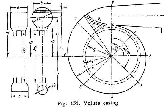
Volute calculation and design are based on the assumption that the peripheral velocity component in the volute varies inversely as the radius (the law of velocity distribution across a vortex section or the law of conservation of angular momentum), i.e.,
![]()
where Г = so-called circulation along a closed curve enveloping the impeller, which is constant for a given volute and given operating conditions.
With the radius increasing the velocity ua decreases and the pressure increases correspondingly. Consequently, a degeneration of the kinetic energy of the fluid into pressure energy takes place in the volute. The process continues in the diffuser beyond the volute (Fig. 151).
The circulation Г can easily be found from the head H generated by the pump and i)h. For, since from Eq. (12.16)
![]()
then, on the basis of the foregoing,
![]()
The rate of discharge through any cross-section of the volute can be assumed to increase in proportion with the angle of inclination of the cross-section a, counting from the initial (and final) section of the volute, i. e.,
![]()
where Q = delivery of pump into pipeline.
For a differential discharge through an area of size b X dr taken in an arbitrary section of the volute at radius r (see Fig. 151)
![]()
whence,

where r3 = (1.03-1.05)r2 is the radius of a cylindrical surface enveloping the impeller to which the volute cross-sections are tangent.
For the simplest case of a volute of rectangular cross-section of uniform width (b = const), we obtain from the foregoing
![]()
By assigning a number of values of a from zero to 360°, we obtain a series of values of #, from r, to Rmax, i. e., the geometry of the volute. For a volute of circular cross-section of variable radius q we have
![]()
where a is the distance from the centre of the section to the impeller centre line and, consequently,

Substituting
in this equation
![]() Q forQα
and
r3
+
ρ
for
a,
and
solving for ρ,
we obtain
Q forQα
and
r3
+
ρ
for
a,
and
solving for ρ,
we obtain
![]() (12.45)
(12.45)
where
![]()
The formula obtained makes it possible to calculate the dimensions and shape of a volute casing of circular cross-section. Calculation of a casing of arbitrary cross-section will involve integration.
59. Selection of pump type. Special features of centrifugal pumps used in aeronautical and rocket engineering
As a rule, the basic criteria governing the selection of pump design are Qy II and n. These quantities enable the specific speed ns to be computed, suggesting the type of rotodynamic pump to be preferred for given conditions. The procedure in calculating centrifugal pump design is outlined in the example in this section.
If the calculations give a very high specific speed (more than 1,200), it means that two or more pumps joined in parallel should be used.
If,
on the other hand, the specific speed turns out to be too low (see
Sec. 56) and the speed of rotation cannot be increased, a
multistage
pump must be used with z
impellers
mounted on a common shaft.
The head developed by each impeller in this case is less by a
factor of z, and the specific speed greater by a factor of
![]() thanin
a single-stage pump.
thanin
a single-stage pump.
I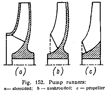 f
such a design is undesir-ablo
displacement pumps are used.
In this case, however, such
fluid properties as viscosity
and chemical activity must
be taken into account.
f
such a design is undesir-ablo
displacement pumps are used.
In this case, however, such
fluid properties as viscosity
and chemical activity must
be taken into account.
In aircraft with gas-turbine engines centrifugal pumps are used mainly as booster pumps in fuel systems. They are usually installed inside the fuel tanks or close to them and are meant to increase the pressure in the whole of the suction pipeline, thereby improving operating conditions for the main fuel pump and minimising the possibility of cavitation.
Booster pumps are commonly made with open, or unshrouded, impellers consisting of a single disk with vanes mounted on one side (Fig. 1526).*
When a booster pump is placed inside a tank a propeller is commonly mounted at the impeller eye (on the same shaft) in order to improve its operating conditions and separate vapour and gas from the liquid. The shaft propeller must be designed for a much higher delivery than the centrifugal pump as some of the liquid delivered by it is hurled away.
Booster fuel pumps usually operate at 6,000 to 10,000 rpm and develop a pressure of 0.6 to 1.2 atm. Their specific speed varies from 100 to 200, that is, they belong to the class of normal- or even highspeed centrifugal pumps.
A recent tendency is to employ centrifugal pumps as the main fuel pumps of gas-turbine engines. The reason is that very high discharge is required and less viscous and more volatile fuels are being used. Centrifugal pumps, furthermore, can operate at very high rotation speeds (several tens of thousands rpm).
In such conditions centrifugal pumps of much smaller size and weight than other types of pumps can ensure the required fuel delivery at sufficiently high pressures. These considerations are also important in selecting pumps for liquid-propellant rocket motors.
In rocket motors centrifugal pumps are widely employed to deliver fuel and oxidiser from the tanks to the combustion chamber. They must generate head high enough to overcome the resistance of pipelines and the pressure in the combustion chamber and to ensure the required pressure difference in the injectors. The required head is several hundreds of metres and the pressure tens of atmospheres.
* The special features of such impellers are analysed further on.
Displacement pumps are commonly used for such high pressures but if a large discharge is also required (as is the case in rocket motors) and there is a possibility of providing a very high-speed drive (e. g., a gas turbine), centrifugal pumps are to be preferred.
With a high impeller rotation speed and appropriate design centrifugal pumps can deliver liquids at high pressure. It follows from Sec. 55 that the appropriate design is the so-called low-speed centrifugal pump with a minimum specific speed.
The designation "low-speed", it should be remembered, refers to the specific speed and is in. no way associated with the actual working speed of rotation, which may be very high.
Thus, the principal feature of centrifugal pumps used in liquid-propellant rocket motors is low specific speed, with all its consequences (see Sections 55 and 56).
In
view of this the impellers of rocket-motor pumps are usually of
the true radial type in which the flow is normal to the axis of
rotation.
Characteristic of such impellers is large relative diameter
![]() and
small relative width
and
small relative width
![]() .
As
mentioned in Sec. 50, lower specific speed means greater relative
energy degradation as a result of
leakage inside the pump (volumetric losses) and friction between
impeller shroud and liquid, i. e., lower r\v
and
r\m
and,
consequently, lower
overall pump efficiency. That is why the efficiency factor of pumps
for rocket motors is usually low.
.
As
mentioned in Sec. 50, lower specific speed means greater relative
energy degradation as a result of
leakage inside the pump (volumetric losses) and friction between
impeller shroud and liquid, i. e., lower r\v
and
r\m
and,
consequently, lower
overall pump efficiency. That is why the efficiency factor of pumps
for rocket motors is usually low.
Impellers may be "closed", or "shrouded", with two disk-like surfaces or walls enclosing the vanes on both sides (Fig. 152a), "semi-open", or "unshrouded", with one disk to which the vanes are attached (Fig. 152b) and, finally, propeller-type with no shrouds and the vanes mounted on the hub (Fig. 152c). In the first two designs backward-curved vanes are used (β2 <C 90°), in the third design the vanes are radially mounted for considerations of strength. Energy losses due to disk friction are much lower in pumps with unshrouded and, all the more so, propeller runners than with closed impellers, but volumetric losses are higher.
The method of calculating the relative friction horsepower described in Sec. 56, can be used for unshrouded impellers with an appropriate coefficient к in the formula for N'f. As to volumetric losses, their determination constitutes a special problem.
Another feature of centrifugal pumps used in liquid-propellant rocket motors is that they usually operate at conditions approaching cavitation owing to their high speeds of rotation. Accordingly, the cavitation estimates set forth before are of special importance.
Example. Calculate to a first approximation the impeller dimensions of a centrifugal pump for a V-2 liquid-propellant rocket motor and determine the required pressure at the pump intake to prevent cavitation. Given:
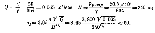
pumped lluid: 75-per cent ethyl alcohol, у = 864 kg/cm1, ht = 44 mm llg; weight rate of discharge of pump: G = 56 kg/sec; pressure developed by pump: ppump = 20.7 atni; rotation speed of impeller: n == 3,800 rpm.
Solution, (i) Determine volume rate of discharge Q, delivered head// and specific speed ns:
(ii) From specific speed and statistical data (see Sees 55 and 50):
![]()
η t — 0.85 (all approximately). Hence,
![]()
(iii) Shaft horsepower:
![]()
(iv) Discharge of liquid through impeller:
![]()
(v) Optimum impeller eye diameter according to Eq. (12.43):
![]()
This is the so-called reduced diameter, which disregards stream contraction by the impeller hub. Taking the latter into account, the equality of areas gives a higher value for Do viz.,
![]()
where d/mb = (1.15-1.25) dsh is the hub diameter;
dsh = shaft diameter determined from strength considerations. Without going into strength calculations, let us assume that DQ=^ 140 mm. The diameter I), is equal to or slightly less than DQ owing to the inclination of the entrance edge of the vanes.
(vi)
Assuming the radial velocity ratio
![]() = 1 andv0
≈
vln
= 1 andv0
≈
vln
![]()
(vii) Assuming initially z = 7, the vane number coefficient is found from Eq. (12.19):
![]()
whence) μ. = 0.77.
(viii)
From
Eq. (12.21') the theoretical head at
![]()
![]()
(ix)
Substituting
v2r
for
the ratio
![]() in Eq.(12.12)
and
solving it as a
quadratic equation,
in Eq.(12.12)
and
solving it as a
quadratic equation,
whence 
(x) Impeller width at exit, taking into account stream contraction by the vanes ψ2 = 0.95:
![]()
(xi) impeUer width at intake (at ψ1), = 0.85):
![]()
(xii) Vane angle at intake for shockless approach of liquid:
![]()
The computed angle p, is usually increased by 3 to 5° to allow for cavitation in case of excessive discharge.
(xiii) Verification of impeller dimensions by repeating calculations in the same order on the basis of finally chosen values for p2 and z and verified values of the coefficients T^μ, \p, i|)2. The latter two are computed from the formulas
![]()
and
![]()
where δ = vane thickness.
(xiv) Radius q of terminal cross-section of volute case according to Eq. (12.45) at a = 360° (assuming r3= 1.05 r2 = 173 mm):

(xv) Required head at impeller eye from Eq. (12.44):
![]()
or, neglecting velocity head,
![]()