

Relative motion and unsteady pipe flow
40. Bernoulli's equation for relative motion
Bernoulli's equation in the form (4.16) is valid for all cases of steady flow when gravity is the only body force acting on a liquid. In aircraft and other machines, however, one frequently encounters cases of a flowing liquid being also subjected to the inertial forces of transport motion when the channel through which it is flowing is itself moving with acceleration. If the inertia force is uniform in time, the flow may be steady with respect to the channel walls and the energy equation can be developed taking into account the work done by the inertia force. This is Bernoulli's equation for relative motion, which is commonly written in the form:
![]() (10.1)
(10.1)
where ΔHln is the so-called inertia head, which represents the difference between the specific potential energies at the second and first cross-sections due to the action of the inertia force or, alternately, the work done by the inertia force referred to unit weight and with the sign reversed.*
Let-us see how the inertia head is calculated for two main cases of steady relative flow corresponding to the two cases of relative rest discussed in Sections 11 and 12.
1. Channel Moving with Uniform Acceleration in a Straight Line. When a channel or pipe with a flowing liquid moves in a straight line with a uniform acceleration a (Fig. 104), all the liquid particles are subject to a constant, uniform inertia force of transport motion. This force may either facilitate or resist the flow.
The
velocity v
and
the acceleration
/, evidently, are the same at all
cross-sections of the 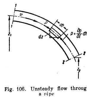 pipe
at agiven
instant.
pipe
at agiven
instant.
We neglect friction losses at first and assume the velocity distribution across the sections to be uniform.
Take a differential cylindrical control volume of length dl and cross-section dS (Fig. 106) and develop its equation of motion.
Projection of the pressure force and the gravity force on the tangent to the centre line of the pipe yields
![]()
or
![]()
As
![]()
then
![]()
(remembering also that p is a function not only of I but of t as well). Integrating along the pipe for a specific moment of time, we have
![]()
or
![]() (10.4)
(10.4)
where
![]()
The equation resembles Bernoulli's equation for relative motion. The term hin is also called the inertia head, not to be confused with
* The sign is reversed because the term has been transposed to the right side of the equation, whereas in developing Bernoulli's equation in Sec. 15 we wrote the work done by external forces on the left side.
R eferred
to unit mass, theinertia
force is equal to the correspon-ding
acceleration a
and
acts
in the opposite direction; the
inertia force acting on each kilogram
of liquid is
eferred
to unit mass, theinertia
force is equal to the correspon-ding
acceleration a
and
acts
in the opposite direction; the
inertia force acting on each kilogram
of liquid is
![]()
The work done by this force in moving the liquid from the first section to the second does not (as in the case of work done by gravity) depend on the geometry of the path and is determined solely by the difference between the coordinates taken in the direction of the acceleration a. Consequently,
![]()
where la = projection of the investigated portion of the channel on the direction of the acceleration.
The following rule, arising from the physical aspects of the phenomenon, is useful to make sure of the sign of &Hin in the right side of the Bernoulli equation.
If the acceleration is directed from the first section to the second and the inertia force is in the opposite direction, the force impedes the flow and the inertia head is positive. The pressure at the second section is lower than at the first and the effect of the inertia head is analogous to the hydraulic losses 2ft, which are always included in the right-hand side of the Bernoulli equation with a "plus" sign.
If the acceleration is directed from the second section to the first, the inertia force facilitates the flow and the inertia bead must be written with a "minus" sign. In this case the inertia head increases the pressure at the second section, i. e., its action opposes the hydraulic losses.
2 .
Rotation of a Channel About a VerticalAxis.
Let a channel or pipe
through which a liquid is flowing be rotating round a vertical axis
with a uniform angular velocity o> (Fig. 105). Acting on the
liquid
will be the inertia force of rotation, which is a function of the
radius. To compute the work done by the force or the change in the
potential
energy due to it integration must be carried out.
.
Rotation of a Channel About a VerticalAxis.
Let a channel or pipe
through which a liquid is flowing be rotating round a vertical axis
with a uniform angular velocity o> (Fig. 105). Acting on the
liquid
will be the inertia force of rotation, which is a function of the
radius. To compute the work done by the force or the change in the
potential
energy due to it integration must be carried out.
The inertia force acting on a unit weight is
![]()
The work done by the force in a displacement dr along the radius is
![]()
The work done in a displacement from a radius r, to a radius r2 (along any curve) is found by integrating the foregoing expression over the interval r^ to r2. Integration gives the value of the inertia head, only the sign must be reversed (as pointed out before, in developing Bernoulli's equation the term is transposed from the left to the right side of the equation). Finally we have
![]()
The sign of the inertia head computed with this formula corresponds to the sign rule explained before.
The Bernoulli equation for these cases of relative motion of an ideal liquid can also be obtained by integrating the differential equations of motion (see Appendix).