

21. Cavitati0n
In some cases of fluid motion in closed conduits there takes place a phenomenon which is due to a change in the physical state of a liquid: vapourisation and evolution of gases dissolved in it.
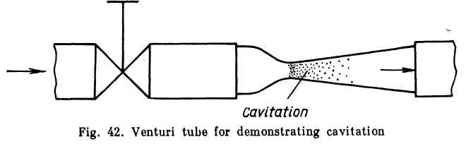
When a liquid flows through a narrowing in a pipe its velocity increases and the pressure intensity decreases. If the absolute pressure drops to the vapour pressure of the liquid for the given temperature, evaporation commences and gases evolve. In short, the liquid simply begins to boil locally. When the stream diverges after the narrowing, the velocity drops, the pressure increases and the boiling stops; the vapour then condenses partially or completely and the gases redissolve.
This local boiling of a flowing liquid is known as cavitation.
A simple device enables the phenomenon to be observed visually. Water or some other liquid is brought under pressure to a valve (Fig. 42) through which it flows into a glass tube with a venturi contraction.
When the valve is opened slightly the discharge is small, the velocity of the stream is low, the pressure drop at the throat of the tube is small and the stream is transparent: no cavitation takes place. The wider the valve is opened, the faster the velocity of the stream mi thee lower the pressure in the narrowing.
At
![]() wherept
is
the saturation vapour pressure, a distinct cavitation
zone appears, which increases in size as the valve is opened
wider.
wherept
is
the saturation vapour pressure, a distinct cavitation
zone appears, which increases in size as the valve is opened
wider.
Cavitation announces itself by characteristic noise and vibrations. Prolonged cavitation has an erosive effect on metal walls. The reason for this is that condensation of the bubbles of vapour takes place very rapidly and the cavities collapse abruptly with high compressive stresses due to local water-hammer effects. The pitting of walls occurs not at the point where the vapour pockets appear but where they collapse.
Cavitation thus has an adverse effect on pipelines and hydraulic systems. When cavitation develops the resistance of pipes increases sharply, with a corresponding reduction in discharge.
Cavitation may develop in any local narrowings followed by expansions, such as faucets, valves, gates, orifices and jets.
In some cases cavitation may also develop when a narrowing is not followed by a diverging section and in straight pipes when the elevation head or energy losses increase.
Cavitation may occur in hydraulic machines, such as pumps or turbines, and on the blades of rapidly revolving ship propeller screws. In these cases the result is a sharp decline in the efficiency of a ma chine and a gradual wearing of its parts.
In aircraft hydraulic systems cavitation may occur because of a reduced barometric pressure with height. In this case the cavitation zone extends over a considerable portion of the low-pressure pipelines (suction pipes) and even along the whole length. When this happens the stream in the pipe divides into a liquid and vapour phase.
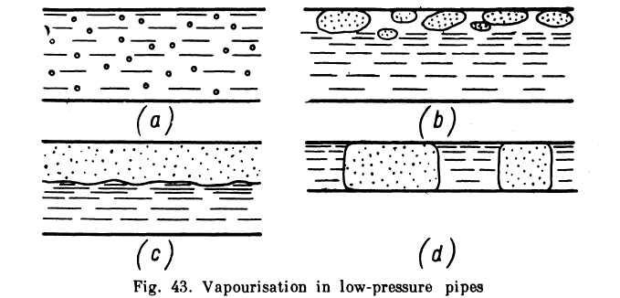
In the initial stage the vapour phase appears as minute bubbler-spread evenly along the flow (Fig. 43a). As vapourisation continue; and the amount of vapour increases the bubbles grow larger and drift along the upper surface of the pipe (Fig. 43b). Finally the liquid and vapour phases may separate completely into two streams, the forme below and the latter above (Fig. 43c). In thin pipes vapour lock may form and the two phases move in intermittent columns (Fig. 43d.)
It is evident that the greater the vapour phase the less the discharge through a pipe. Condensation (partial or complete) of the vapour takes place in the pump of a system, where pressure increases sharply, or in the pressure pipe through which the liquid is pumped to the consumer.
Cavitation phenomena are different in plain (simple) and component (complex) liquids. In a plain liquid the pressure at which cavitation occurs corresponds to the saturation vapour pressure, which depends only on temperature. The phenomena were described above.
A component liquid consists of so-called light and heavy fractions. The lighter fractions have a higher vapour pressure and the start boiling before the heavy ones. Condensation takes place in the reverse order.
Multicomponent liquids containing light fractions are more subject to cavitation and the vapour phase persists longer, but the process is not so pronounced as in plain liquids.
Example. Determine flow conditions of АМГ-10 fluid in a pipe of an aircraft hydraulic system if the pipe diameter d — 12 mm, the rate of discharge Q = 0.25 1/sec and the temperature is zero centigrade (see Table 1 on p. 24). At what temperature will flow conditions change?
Solution, (i) From Table 1, v = 42 cst == 0.42 cm2/sec.
(ii) The Reynolds number is
![]()
The flow is laminar.
(iii) The viscosity corresponding to the change of the flow regime is
![]()
(iv) Plotting a graph of the coefficient v as a function of temperature from the data in Table 1, we find that tcr = 40°C.