

12. Liquid in a uniformly rotating vessel
 Let
us first consider an open cylindrical vessel containing a liquid id
revolving about its vertical axis with an angular velocity ω. The
liquid gradually attains the same angular velocity as the vessel id
its free surface becomes a concave surface of revolution (Fig. 20).
Acting
on the liquid are two body forces, gravity and a centrifugal
force, respectively equal to g
and
ω
2r
when referred to unit mass, ue
to its second component, the resultant body force j
increases ith
the
radius while its inclination to the horizontal decreases, lis
force
is normal to the free surface, owing to which the inclination
of the surface increases with the radius.
Let
us first consider an open cylindrical vessel containing a liquid id
revolving about its vertical axis with an angular velocity ω. The
liquid gradually attains the same angular velocity as the vessel id
its free surface becomes a concave surface of revolution (Fig. 20).
Acting
on the liquid are two body forces, gravity and a centrifugal
force, respectively equal to g
and
ω
2r
when referred to unit mass, ue
to its second component, the resultant body force j
increases ith
the
radius while its inclination to the horizontal decreases, lis
force
is normal to the free surface, owing to which the inclination
of the surface increases with the radius.
Let us develop the equation of the curve AOB for a z-r coordinate system with the origin at the centre of the bottom of the vessel. Since the force j is normal to the curve AOB, we find 4rom the drawing that
![]()
Hence,
![]()
and, integrating,
![]()
From the stated conditions it follows that at the intersection of fecurve AOB with the rotation axis C = h, whence we finally have
![]() (3.2)
(3.2)
i. e. curve AOB is a parabola and the free surface is a paraboloid of revolution.
Equation (3.2) can be used to determine the position of the free surface in the vessel, for instance, the maximum rise H of the liquid and the elevation of the summit of the paraboloid at a given velocity of rotation ω. For this, however, the volume equation must be employed in which the volume of liquid at rest is equal to its volume during rotation.
A more common case in practice is when a vessel containing a liquid revolves about a horizontal or arbitrary axis and the angular velocity ω is so great that gravity can be neglected as compared with the centrifugal forces.
The pressure gradient in the liquid can easily be obtained by considering the equilibrium equation for an elementary volume of base area dS and height dr taken along the radius (Fig. 21). The volume is subjected to pressure and centrifugal forces. Let p be the pressure at the centre of area dS, r the distance of dS from the axis of rotation, p + dp the pressure on the second face of the volume, and r + + dr the distance of the latter from the axis. The equilibrium equation for the volume in the direction of the radius is
![]()
or
![]()
whence, integrating,
![]()
The constant C is found from the condition that, at r = r0, p=p0, whence
![]()

Finally, we obtain the relation between p and r in the form
![]() (3.3)
(3.3)
The surfaces af equal pressure are evidently circular cylinders whose centre lines are on the axis of rotation of the liquid. If the vessel is only partially filled, the free surface, as one of the surfaces of equal pressure, is a cylinder of radius r0 and the pressure is p0.
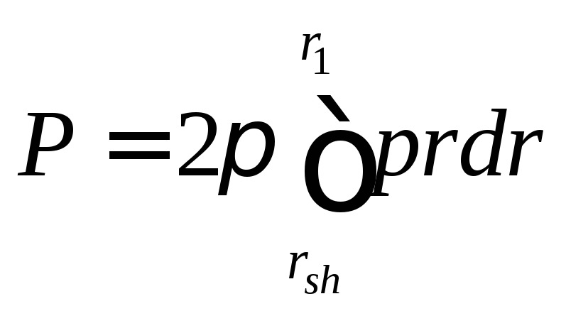
It is frequently necessary to calculate the thrust of a liquid rotating with a vessel exerted on the wall normal to the axis of rotation (or on a ring section of the wall).
F or
this the thrust on an elementaryring
surface of radius r
and
width dr
must
be determined from Eq. (3.3):
or
this the thrust on an elementaryring
surface of radius r
and
width dr
must
be determined from Eq. (3.3):

integration of this equation gives the solution.
If a liquid is made to rotate very quickly the thrust on the walls may be considerable. This is utilised in certain types of friction clutches in aircraft engines where considerable normal pressures are required for the torque to be transmitted from one shaft to another. The method described here is used to calculate the axial pressure of a liquid on the impellers of centrifugal pumps.
The same equations for the examined cases of relative rest can be developed by integrating the differential equations of fluid equilibrium (see Appendix).
Example. Determine the axial thrust acting on the impeller of a centrifugal pump in a Walter liquid-propellant rocket if in the spaces Wml and W2 (Fig. 22) between the impeller vanes and the pump casing the liquid rotates with an angular velocity equal to half the velocity of the impeller and the leakage at A is small enough to be neglected.
The discharge pressure pa = 38 atm, intake pressure p, = 0, speed of rotation n = 16,500 rpm; impeller dimensions: ra ~ 50 mm, r, = 25 mm, rsh = 12 mm; specific weight of fluid v = 918 kg/m8.
Solution. The thrust exerted by the fluid on surfaces AB and CD is balanced. The only unbalanced force is the axial pressure on surface DE} i. eM a ring area bounded by circles of radii rx and rsh. The required force is directed to the left and is equal to .
where, from Eq. (3.3) and substituting pa and ra for p0 and r0, respectively,
![]()
where
![]() = angular speed of rotation of the fluid.
= angular speed of rotation of the fluid.
Hence,

whence, substituting the numerical values we obtain

CH APT E R IV