

Chapter XII centrifugal pumps
48. General concepts
A pump is a machine which imparts head to a fluid.
From the physical aspect, the work of a pump consists in transforming the mechanical energy of a motor (drive) into fluid energy, i. e., in imparting power to a flow of fluid passing through it. The energy imparted to the fluid in the pump enables the former to overcome hydraulic resistances and rise to a geodetic elevation.
The energy imparted to each kilogram of fluid in a pump, i. e., the specific energy increase, is linear in dimension and, as mentioned before, represents the pumping head. It was stated in Sec. 47 that the pumping head
![]()
or
![]()
Thus, in the general case the pumping head is the sum of the increase in pressure head (static head) and the increase in specific kinetic energy (dynamic head).
The second term, however, is usually much smaller than the first and if the intake and outlet pipes have the same diameter (dt = d2, whence vi = v2) and at = a2, it is zero and
![]() (12.1)
(12.1)
The rate of discharge of a pump is also called its delivery or capacity, denoted Q.
The power of a pump is defined as the energy imparted by the pump to the fluid flow per second:
![]()
Like any other driven machine, a pump consumes more power than it gives off. The ratio of the actual power developed by the pump (the "water horsepower") to the power supplied by the pump (the "shaft horsepower") gives the efficiency of the pump:
![]()
Hence, the shaft horsepower
![]()
and, taking into account Eq. (12.1),
![]()
This is the formula used in choosing pump drives.
Total, or overall, pump efficiency takes into account three types of energy losses: hydraulic losses due to fluid friction and turbulence, volume losses due to leakage through internal passages, and mechanical losses due to mechanical friction in bearings, packings, etc.
Pumps used in aeronautical engineering seem to vary enormously in design and principle of action. Nevertheless, they can all be divided into two main types:
1. Rotodynamic pumps, to which belong radial-flow centrifugal, mixed-flow and axial-flow or propeller pumps;
2. Displacement pumps, which include reciprocating and rotary pumps.
This chapter is devoted to centrifugal pumps, which are finding growing application in aeronautical and rocket engineering.
49. The basic equation for centrifugal pumps
A centrifugal pump operates in the following manner.The principal working unit is a vaned rotor, called an impeller (Fig. 131), which is made to revolve at high speed. It accelerates the incoming fluid, increasing both the pressure and absolute velocity of the latter, driving it to the outlet of a spiral casing (the volute). By virtue of force interaction between the vanes and the fluid , the mechanical
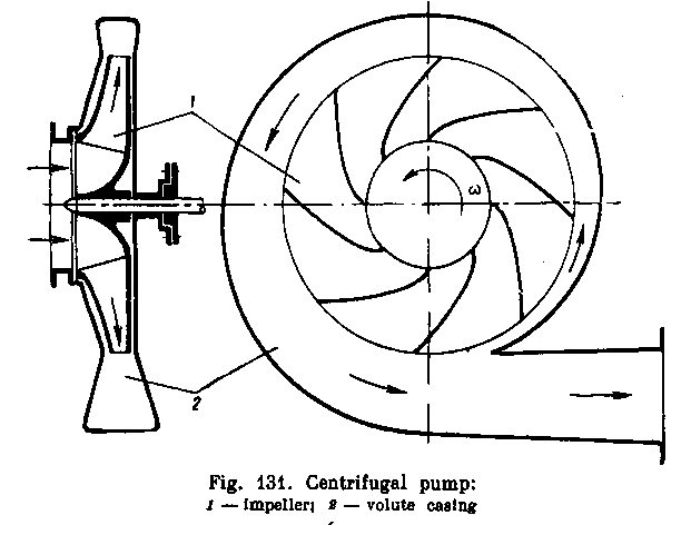
energy of the drive is transformed into the energy of flow.
The volute casing guides the fluid to the pump outlet; in the volute the kinetic energy of the fluid is partly converted into pressure energy.
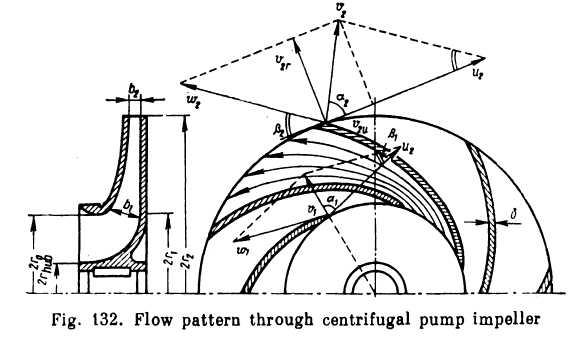
The impeller of a centrifugal pump (Fig. 132) consists of two disk-like walls, sometimes called "shrouds", one of which is mounted on the shaft. The other shroud, coupled to the former by the vanes, has a hole in the centre, called the "eye". The vanes are curved, cylindrical or have more complex surfaces. The fluid enters the impeller along the axis of rotation through the eye, flows radially outward between the vanes, and is discharged around the entire circumference into the casing.
The motion of the fluid through the passages betweenlhe vanes can be regarded as consisting of two motions: motion of transport (rotation of the impeller) and motion relative to the impeller. Hence, the absolute velocity vector v of the fluid can be found as the vector sum of the peripheral velocity и and the relative velocity w. Taking a fluid particle sliding along a vane, one can construct a velocity parallelogram for the entrance of the particle to, and discharge from, the vane, assuming the relative velocity w to be tangent to the vane and the peripheral velocity и tangent to the corresponding circle. A similar velocity parallelogram can be constructed for any point on the vane. The subscript 1 refers to the entrance section, and subscript 2 to the exit section of the vane.
The angle between the vectors of the peripheral and absolute velocities is at and the angle between the tangent to the vane and the tangent to the circumference of the impeller drawn in the opposite direction of the rotation is (i, with the corresponding subscripts. In the general case the angle a changes with the pump performance, i.e., with the speed of rotation n of the impeller (the velocity u) and the discharge Q (the velocity w). Angle P determines the inclination of a vane at every point and, consequently, does not depend on pump performance.
In order to develop the basic equation of centrifugal pump theory, we shall accept the following two assumptions:
The impeller consists of an infinite number of uniform vanes of zero thickness (z = oo, б =0). This means that we assume such flow in the passages between the vanes in which the geometry of all the stream tubes in the relative motion is identical and corresponds exactly to the vane geometry, and that the velocities depend only on the radius and are the same on a circle of given radius. This is possible in the case when each differential stream tube is guided by its vane. Such flow is shown schematically for one vane passage in Fig. 132.
The pump efficiency is unity (т) = 1), i. e., there are no energy losses in the pump and shaft horsepower is converted completely into water horsepower. This is possible in the case of an ideal fluid, no leakage in the pump and no mechanical friction in packings and bearings.
Thus, to facilitate our theoretical investigation of a centrifugal pump we have substantially idealised its performance. We shall call such a centrifugal pump, in which z — oo and ц = 1, an ideal
pump. After considering the theory of the idealised pump we shall, naturally, proceed to deal with real pumps.
Let us develop two equations: the power equation and the equation of moments. The former means that the power supplied to the impeller shaft is equal to the energy imparted every second to the fluid in the pump, viz.,
![]() (12.5)
(12.5)
where T = torque on impeller shaft;
o) = angular velocity of impeller;
Ht<3> = head developed by theoretical idealised pump or increase of specific energy of fluid in pump (the subscripts "Г and "oo" corresponding to the two assumptions made before).
The meaning of the second equation is as follows: The torque acting on the pump shaft is equal to the increase in the angular momentum of the fluid in the impeller per second. Denoting by ri the radius of the cylindrical surface on which the entrance edges of the vanes are located, and by r2 the peripheral radius of the impeller, we have
![]() (12.6)
(12.6)
From Eqs (12.5) and (12.6) the head delivered by an idealised pump is
![]() (12.7)
(12.7)
This is the basic equation not only for centrifugal pumps but for all rotodynamic machines, such as fans, compressors and turbines. In the case of turbines the angular momentum of the fluid flowing through the rotor decreases, i.e., energy is dissipated, and the signs of the terms in the parentheses should be reversed. Equation (12.7) was developed by Euler and bears his name.
Attention should be paid to the fact that the head delivered by an idealised centrifugal pump in terms of column of pumped liquid does not depend on the type of liquid (i. e., on its specific weight).
As a rule, a liquid entering the impeller has no whirl component.* In the vane passages it moves in radial direction. This means that the vector vi is pointed along the radius and the angle ai = 90°.
♦ In some machines prerotation is produced by a
special vane or worm wheel mounted
before the impeller (see further on).
In some machines prerotation is produced by a
special vane or worm wheel mounted
before the impeller (see further on).
Consequently, the second term in Eq. (12.7) vanishes and the equation takes the form
![]()
where u2 = (or2 = peripheral velocity at vane exit;
v2u = projection of absolute exit velocity on direction of peripheral velocity, i. e., the tangential component of velocity v2.
Equation (12.8) shows that for a centrifugal pump to deliver a high head the peripheral velocity must be great and, secondly, the vector i;2umust be large enough, i. e., sufficient whirl should be imparted to the fluid. The former is achieved by increasing the speed of rotation and impeller diameter, the latter is attained by providing a sufficient number of vanes of suitable size and shape.