

37. Flow through tubes and nozzles
A tube is a short unrounded pipe whose length is only several diameters [l = (2-6)d] (Fig. 88a). An orifice in a thick wall is actually a tube (Fig. 88b).
Two flow regimes are observed in efflux of a liquid through tubes with unrounded edges into a gas. The first regime is shown schematically in Fig. 88a and b. On entering the tube the jet converges and forms a vena contracta in about the same way, and for the same reason, as in the case of a free jet through an orifice in a thin wall. Then

the jet expands and issues from the tube in a stream of the same diameter as the pipe. Between the vena contracta and tube walls a zone of violently eddying liquid is formed. As the jet has the same diameter as the aperture, ε = 1 and, consequently, μ = φ. For low-viscous liquids the mean values of the coefficients are
![]()
![]()
The rate of discharge through a circular tube running full (first regime) is greater than through an orifice in a thin wall; the velocity, on the other hand, is less owing to greater friction.
Consider a jet of liquid issuing under pressure p0 into a gas having pressure p2 (say, into the combustion chamber of a liquid-propel-lant rocket motor). The rated head for unsuppressed contraction is
![]()
As the pressure in the jet at the tube outlet is p2, at the vena contracta inside the tube, where the velocity is greater, the pressure px is lower than p2. Furthermore, the higher the head under which the jet is issuing, and consequently the greater the rate of discharge, the less the absolute pressure in the vena contracta. The difference p2 — p1 varies as the head H. This is demonstrated by Bernoulli's equation written between sections 1-1 and 2-2 (Fig. 88a) in the form
![]()
The last term is the loss of head due to jet expansion. This is completely analogous to an abrupt expansion, hence the loss of head due to expansion is given by Eq. (8.1). The vena contracta is determined by the same coefficient of contraction as in flow through an orifice. Therefore, from the continuity equation,
![]()
Using
this formula to eliminate vx
from
the foregoing Bernoulli equation
and writing the velocity v2
in
terms of the velocity coefficient
of the tube,
![]() we
obtain the pressure drop insidethe
tube:
we
obtain the pressure drop insidethe
tube:
 (9.13)
Substitution of the values cp = 0.82 and e = 0.64 into this expression yields
![]() (9.13`)
(9.13`)
At some critical head Hcr the absolute pressure at section 1-1 in the tube becomes zero and
![]()
But
at H
>
Hcr
this
would mean a negative pressure px
which
is
practically impossible in liquids; it follows then that at H
>
Hcr
the
first flow regime (tube running full) is impossible. This is
confirmed
experimentally, and at
![]() the
flow regime changes suddenly.
The jet springs clear of the walls of the tube and issues from
it as shown in Fig. 88c.
the
flow regime changes suddenly.
The jet springs clear of the walls of the tube and issues from
it as shown in Fig. 88c.
This regime is identical to efflux through an orifice in a thin wall and it is characterised by the same jet coefficients. Thus, in a changeover from the first flow regime to the second the velocity increases and the rate of discharge, owing to jet contraction, decreases.
For the case of a jet of water into the atmosphere running clear
![]()
A submerged jet through a tube cannot run clear and the first regime persists at H>Hcr. With the head H increasing, however, the discharge coefficient drops and as a result of cavitation inside the tube the loss coefficient increases.
It follows, thus, that circular tubes possess some appreciable shortcomings: in the first regime (running full) resistance is great and the coefficient of discharge is small; in the second regime (running clear) the coefficient of discharge is even less. Furthermore, the flow regime through cylindrical tubes is unstable.
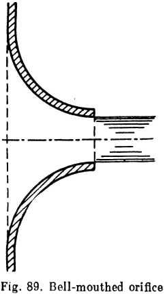
For these reasons cylindrical tubes are not favoured and, in fact, they are almost never specially provided for (with the exception of some liquid-propellant rocket motors). In engineering practice, however, tubes are frequent as bores in thick walls. Their performance can be improved substantially by rounding the inlet edge (broken lines in Fig. 88b). The greater the curve the higher the coefficient of discharge and the lower the loss coefficient. In the limit, when the radius of curvature equals the thickness of the wall, the circular tube becomes a bell-mouthed orifice (Fig. 89).
A bell-mouthed orifice is a widely used type of mouthpiece with a coefficient of discharge approaching unity, low losses, no vena con-tracta, a stable flow regime and a firm jet.
The loss coefficient is about the same as for a gradual contraction
![]()
the lower values of ζ corresponding to high Reynolds numbers and vice versa.
Correspondingly,
μ =φ = 0.99-0.96.
A diffuser mouthpiece (Fig. 90) is a diverging taper pipe affixed to a bell-mouthed orifice. Addition of a tail-pipe leads to lower pressure at the throat of the tube and, consequently, higher velocity and rate of discharge. The discharge of a bell-mouthed orifice can be increased by as much as 2.5 times by the addition of a diverging mouthpiece.
Such mouthpieces are used when the discharge for a given head must be as high as possible through a small orifice. Application, however, is limited to low heads (H = 1-4 m) as otherwise cavitation

develops in the throat, with a resulting increase in resistance and reduction of rate of discharge.
The diagram in Fig. 91 shows how the coefficient of discharge of a diverging mouthpiece is affected by the head increasing due to cavitation at the throat. The discharge coefficient is referred to the cross-sectional area of the throat, i. e.,
![]()
The curve was obtained in tests with a cone having an optimum angle and rate of divergence ensuring the highest coefficient of discharge.

Example. In some liquid-propellant rocket motors the fuel components are supplied into the combustion chambers through so-called spray injectors which are simple boreholes. Determine the required number of oxidiser injectors for the motor of a Schmetterling rocket if G = 1.6 kg/sec, pressure drop in injector Δр = 6 kg/cm2, pressure in the chamber p2 = 25 kg/cm2, orifice diameter d0 =. 1.5 mm, ratio of wall thickness to orifice diameter d/d0 = 0.5. The oxidiser is nitric acid, specific weight y = 1,510 kg/m8, kinematic viscosity v = 0.02 cm2/sec.
How many injectors would be required if 6/d0 = 2.5?
Solution, (i) Theoretical velocity of efflux:
![]()
Reynolds number:
![]()
The graph in Fig. 84 gives the coefficient of discharge as a function of Ret: μ= 0.62.
Total area of all injector mouths:
![]() sq cm
sq cm
Number of injectors:
![]()
If the bore ratio were6/do= 2.5, the efflux would be as from an external cylindrical tube. To determine the flow regime find /±pcr Eq. (9.13 ) gives
![]() kg/cm²
kg/cm²
As bpcr > AP, the first flow regime (running full) will obtain and the coefficient of discharge is \i = 0.82. Consequently,
![]()