

47. Pipeline with pump
The foregoing discourse dealt essentially with isolated sections of plain and compound pipelines, not with complete systems of liquid supply (with the exception of the simplest gravity flow system). It was mentioned, furthermore, that in aeronautical engineering forced flow by means of pumps is the main method of liquid supply. Let us investigate the operation of a pipeline with a pump and the principles for calculating such pipelines.
A pipeline with pump may be open, if the liquid is pumped from one place to another, or closed (looped) if a constant volume of liquid is recycled.

We shall first consider an open pipeline (Fig. 122) in which the liquid is driven by pump from, say, a reservoir where tbfe pressure is p0 to the combustion chamber of an engine where the pressure is p3 or to another reservoir.
The elevation of the pump shaft above the lower level #, is the geodetic suction head, the pipe along which the liquid flows to the pump being the suction, or intake, pipe or line. The elevation of the end section of the pipeline, or the upper level of the liquid (#2), is the geodetic delivered head and the pipe through which the liquid travels from the pump is called the pressure, or discharge, or outlet pipe or line.
Bernoulli's equation for the motion of the liquid in the suction line, i. e., between sections 0-0 and 1-1, yields

This equation shows that the pump develops suction (lifts the liquid to the height Ht)y imparts kinetic energy to the liquid and overcomes hydraulic resistances by expending the pressure po.As this pressure is usually very limited, it should be expended in such a way as to continuously maintain some pressure reserve px at the pump intake, which is essential for the pump to work without cavitation. It stands to reason that suction lines should therefore be calculated with special care.
Equation (11.11) is the basic formula for this.
The following solutions may be required to calculate a suction pipeline.
1. Given dimensions and rate of discharge. To determine absolute pressure at pump intake.
The solution of the problem is a verification estimate for the suction line. The absolute pressure pt as found from Eq. (11.11) is compared with the minimum permissible pressure for the case under consideration.
2. Given minimum permissible absolute pressure pimin at pump intake. To determine one of the following permissible limiting quan tities:
![]()
Determination of the last quantity is of special importance in aircraft hydraulic systems, in which p0 = paim + Δp. Here Δp is the pressure above atmospheric pressure produced by supercharging or the pressure of an inert gas. The minimum permissible atmospheric pressure patni min is determined from pomin, then the maximum permissible altitude of flight for an aircraft equipped with such a system is determined from a standard atmosphere table.
An increase in the pressure p0 increases the pressure in the whole of the siiction line, which makes for greater altitude range of the system. On the other hand, high pressure in the supply tank means stronger walls and, consequently, greater weight of the tank. Therefore greater altitude range of aircraft hydraulic systems is usually attained by installing an additional pump at the beginning of the suction line to produce a higher pressure in the latter, thereby preventing cavitation at the intake of the main pump.
Bernoulli's equation for a liquid in the pressure pipe between sections 2-2 and 3-3 yields
If the pressure pipe discharges into a reservoir there is no velocity head in the right-hand side of the equation, but the loss of head due to enlargement must be taken into account.
The left-hand side of Eq. (11.12) represents the specific energy of the liquid at the pump outlet.
The specific energyat the intake can be found from Eq. (11.11).
![]()
Let us find the increase in the specific energy of the liquid in the pump, i. e., determine the energy obtained by every kilogram of the Hquid in passing through the pump This energy is imparted by the pump, and it is called the pumping head, denoted Hpamp. To determine Hpamp, subtract the last equation from Eq. (11.12):

or
![]()
where Δz = total geodetic elevation of liquid (see Fig. 122);
![]()
kOm = total hydraulic losses in suction and pressure pipings
If
we add to the actual change in elevation Δz
the
pressure head difference
![]() we
consider an equivalent added lift
we
consider an equivalent added lift
![]()
and Eq. (11.13) can be rewritten
![]()
Compare the expression (11.13) with the required head formula in (11.6). It is evident that
![]()
This equality can be extended to all cases of steady operation of a pump in a pipeline and formulated as a rule: In the case of steady flow in a pipeline the head developed by the pump is equal to the required head. This is the only condition of steady pump performance. Usually it is maintained automatically.
Equation
(11.14) is the basis for a method of calculating pipelines with
pumps which consists in plotting two curves to the same scale on
one diagram—the characteristic curve of the pipeline
![]() and the characteristic curve of the pump
and the characteristic curve of the pump
![]() -
and
finding their point of intersection (Fig. 123).
-
and
finding their point of intersection (Fig. 123).
Pump characteristics will be discussed in greater detail later on in a special chapter. Still, running ahead somewhat, the following definition must be given: the characteristic of a pump is defined as the dependence of the pumping head on the delivery (rate of discharge) at a constant speed of rotation.
The intersection of the pipeline characteristic and the pump characteristic locates the point of equality between the required head and the pumping head, i. e., Eq. (11.14). This is known as the operating point. The pumping regime is always maintained, as far as possible, so as to correspond to that point.
To
obtain another operating point the opening of the control v alve(i.
e., the pipeline characteristic), or the pump's rpm must be changed.
This will be discussed in detail later on.
alve(i.
e., the pipeline characteristic), or the pump's rpm must be changed.
This will be discussed in detail later on.
It should be remembered, however, that this analytical method of determining the operating point is applicable only when the rotation speed of the pump drive does not depend on the power input, i. e., the load on the pump shaft. This is possible when a pump is driven by an alternating-current electric motor or an aircraft engine whose power is many times greater than the power of the pump.
If a pump is driven by a special internal-combustion engine or turbine, the power of which depends

on the pump shaft load, the calculation must necessarily be different. The curves of required and available power must be plotted against the number of revolutions per minute and their point of intersection will then give the operating speed and power.
For a looping pipeline (Fig.. 124) the geodetic elevation of the liquid is zero (Δz = 0), and, con sequently, at vi = v2,
![]()
i. e., the same equation is valid for the required head and the pumping head.
A looping pipeline must always be provided with a so-called expansion or compensation tank, usually tapped at the pump intake where pressure is lowest. Without such a tank the absolute pressure inside the pipeline would be unsteady and would also vary with- temperature and due to leakage.
With an expansion tank tapped to the pipeline as shown in Fig. 124 the pressure at the pump intake becomes steady and equal to
![]()
When Pi is known, the pressure at any cross-section of the loop can be calculated. If the pressure p0 in the tank changes, the pressure at any point in the system will change by the same value, i. e., Pascal's law of the transmission of pressure in a still liquid (see Sec. 6) is valid. The tank can also be tapped to the loop as shown in Fig. 149.
Example 1. Determine the required head at the outlet of a booster pump in an aircraft fuel system to supply T-l fuel at a rate of G = 1,200 kg/hr from the service tank to the engine fuel pump if the length of the duralumin piping is / = 5 m, diameter d = 15 mm, required pressure at fuel-pump ftitake p% =* = 1.3 kg/cm8, kinematic viscosity of kerosene у =» 0.045 cm2/sec, specific weight yk— 820 kg/m*. Local disturbances in piping are shown in Fig. 125. Neglect elevation of liquid in tank.
Solution, (i) Velocity of flow in pipeline:
![]()
(ii) Reynolds number]
![]()

![]()
(v) Pressure drop in pipeline from booster pump to fuel pump:

(vi) Hence the required pressure at the booster pump outlet is
![]()
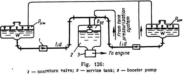
Example 2. Referring to Fig. 126, fuel T-l is delivered from two under-wing tanks to the service tank by higher pressure in the former: Δр = puw — pst =0.2 kg/cm2.
Determine
the diameter d
of
the piping if the two under-wing tanks are to be
emptied simultaneously and the total rate of discharge of the fuel
is G
=1500 kg/hr. The volume of each under-wing tank W
=
450 lit. The piping is
of duralumin, I = 7m, Kinematic viscosity of kerosene v = 0.045
cm2/sec,
specific
weight γk
= 830 kg/ms.
Neglect height of liquid columns in under-wing tanks.
is
of duralumin, I = 7m, Kinematic viscosity of kerosene v = 0.045
cm2/sec,
specific
weight γk
= 830 kg/ms.
Neglect height of liquid columns in under-wing tanks.
Solution, (i) Time of engine operation until under-wing tanks are emptied:
![]()
(ii) Rate of discharge from each tank.
![]()
(iii) Assign several pipe diameters: d = 12; 14; 16; and 18 mm.
(iv) Table 2 gives loss coefficients at pipe entrance ζentrancei nonreturn valve ζvalve elbow ζelbow tee ζtee pipe outlet ζitoutie. After determining Re compute the friction factor λt according to Konakov for each value of d.
(v) Determine the required head Hreq for each value of d from the formula
![]()
and plot curve Hreq = f(d) (Fig. 127).
(vi) Dividing Δp by yki determine available head and from diagram find required diameter, which is d = 15.7 mm.
Hence, the commercial pipe diameter to ensure the required flow rate for simultaneous delivery of fuel from under-wing tanks is d = 16 mm.
If the pipelines were of different length, their diameters would also have to be different for the given set of conditions and the curves Hreq=f(d) would have to be constructed for each pipeline.
Example 3. When an airplane is refuelled under pressure all the tanks must be filled simultaneously. A block diagram of the refuelling system is shown in Fig. 128.
Let all the tanks lie in a horizontal plane at an elevation ht over the refueller pump. The elevation of the fuel main А В above the pump is hA. The characteristic of the refuelling pump, the length lsi and diameter dsl of the filling sleeve, the length of all pipelines and the volumes of the tanks are given.
Neglecting the height of the liquid columns in the tanks and the gauge pressure in them, solve the following commonly occurring engineering problems:
(I) Determine the refuelling time T if the diameters of the piping are given.
(II) Determine the required pipe diameters dm, dv cfo, dt to ensure the simul taneous filling of all the tanks in time T.
(I) The solution is graphoanalytical.
(i) Plot characteristic curve of filling sleeve from pump to the filling connection A.
(ii) Plot characteristic curve for fuel main from A to B.
(iii) Sum both curves according to the rule of compound pipes in series (Fig. 129).
(iv) Plot characteristics for piping from the cross at В to respective tanks.
(v) Sum characteristics in (iv) according to the rule for compound pipes in parallel.
(vi) Summation of the net characteristic of the four parallel pipes and the pipe characteristic from the pump to В gives the characteristic curve of the whole composite pipe system.

( vii)
The intersection of the pipeline characteristic
with the refuelling pump characteristic gives the
pumping head Hpump
and
the rate of discharge of the pump Qpamp.
vii)
The intersection of the pipeline characteristic
with the refuelling pump characteristic gives the
pumping head Hpump
and
the rate of discharge of the pump Qpamp.
(viii) The rate of discharge into each tank is determined as shown in Fig. 129.
(ix) The refuelling time T (when all tanks are filled simultaneously) is
(II) The solution is graphoanalytical. (i) Determine the rate of discharge Qpump of the refuelling pump necessary to fill all tanks in time T by dividing the total tank volume by T.
(![]() ii)
Locate the operating point on the pump characteristic
according toQpump,
i.
e.,
the pumping head
Hpamp.
The
pipe diameters must be so selected as
to ensure a rate of discharge equal to Qpamp
when
the head is HpJ{mp,
ii)
Locate the operating point on the pump characteristic
according toQpump,
i.
e.,
the pumping head
Hpamp.
The
pipe diameters must be so selected as
to ensure a rate of discharge equal to Qpamp
when
the head is HpJ{mp,
(II) Determine the rate of discharge through each pipe by dividing the volume of each tank by the time T.
(iv) Determine the loss of head H5t in the filling sleeve, taking into account the minor losses in the nonreturn valve of the filling connection.
(v) Plot the loss of head as a function of the diameter of the fuel main between A and B: Ha-b = f(d). For this assign several diameter values and for each d determine: the Reynolds number Re, the friction factor lt, and the loss of head Ял-в, including the difference between the elevation heads of the fuel main and the refueller pump hA and losses in the sleeve Hsl.
(vi) Plot the head losses as a function of diameter for each pipe to the respective tanks.
The
construction is the same as that of the curve![]() ,
but
the origin
of the coordinate axes is taken at point Нрищр,
the
positive direction of the diameter
axis being to the left and of the head axis, downwards (Fig. 130).
Add
to thie head losses the head htank
—
hA.
,
but
the origin
of the coordinate axes is taken at point Нрищр,
the
positive direction of the diameter
axis being to the left and of the head axis, downwards (Fig. 130).
Add
to thie head losses the head htank
—
hA.

This
rather unusual directing of the coordinate axes and the curves
![]() for the respective pipings simplifies the determination of the
required diameters.
for the respective pipings simplifies the determination of the
required diameters.
Assign a diameter dm of the fuel main and, from the diagram, determine the diameters du d% , dt as shown by arrows in Fie. 130. The diagram can be used to determine several diameters from which tne most economical can be chosen.
Point
В
on
curve
![]() shows
the loss of head HB
between
the pump and
the cross. The remaining head
shows
the loss of head HB
between
the pump and
the cross. The remaining head
![]() is
used to overcome the resistances
to the flow through the pipes to the tanks and the elevation hiank
—
hA.
is
used to overcome the resistances
to the flow through the pipes to the tanks and the elevation hiank
—
hA.
This
method of problem solution can be employed when the pipes to the
respective
tanks branch at different points; in this case three curves have to
be plotted
instead of a single curve
![]() .
.