

The basic equations of hydraulics
13. Fundamental concepts
We shall commence our study of liquids in motion with an examination of so-called ideal-fluid flow. An ideal fluid is an imaginary fluid whose viscosity is zero. As in real motionless fluids, the only strains possible in a nonviscous fluid are normal compressive strains; i.e., pressure forces.
Pressure forces in a flowing ideal fluid possess the same properties as in a motionless fluid, i. e., on the boundary they are directed along the inward normal; at any point inside the fluid they are the same in all directions.*
Flow may be steady or unsteady.
In steady flow the flow characteristics at a fixed position in space do not change with time; pressure and velocity change only with the change of position of a fluid particle. Mathematically this can be expressed as follows:
![]() ;
; ![]()
![]() ;
; ![]() ;
;![]() ;
;![]()
where the velocity subscripts denote the respective projections on a set of cartesian axes.
In the general case of unsteady flow, pressure and velocity vary with both position and time, i. e.,
U nsteady
flow is observed when A liquid pours under gravity out
nsteady
flow is observed when A liquid pours under gravity out
of a sink in the bottom of a vessel and in the suction, and
pressure pipes of an ordinary reciprocating piston pump.
Steady flow is observed when a liquid is flowing out of a vessel
in which a constant level is maintained or in a looped pipeline
through which a liquid is driven by a centrifugal pump with a
uniform speed of rotation.
Ivestigation of steady flow is much simpler than of unsteady flow. In this book we shall consider mainly steady flow, only touching on some special cases of unsteady flow.
In steady flow the fluid particles travel along pathlines which do not change with time.
In unsteady flow different particles passing through a given point in space will be moving along different pathlines. Accordingly, to investigate the flow pattern for every given moment of time the concept of streamline is introduced.
A streamline is a line in a flowing fluid the tangent to which at any point shows the direction of the velocity vector of the fluid particles at that point (Fig. 23). In steady flow, evidently, streamlines and pathlines coincide and do not change with time.
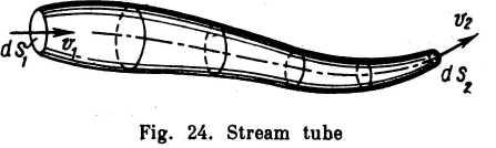
A stream tube is a tubular space bounded by a surface consisting of streamlines (Fig. 24). When the cross-section of a stream tube is contracted to zero, a streamline is obtained in the limit.
The velocity vectors at all points of the surface of a stream tube are tangential to the surface. There being no normal components of the velocity, no particle of the liquid can enter or leave the stream tube, except at the ends. Thus, a stream tube can be regarded as surrounded by impenetrable walls and therefore treated as an elementary stream.
At first we shall imagine streams of finite size as being made up of bundies of elementary stream tubes. Due to differences in velocity the stream tubes slip with respect to one another, but there is no mixing.
* The latteris proved in the samp way as for a motionlees fluid (see Sec 5) the equations of motion are developed for an elementary tetrahedron, taking into account the D’Aiembert inertia forces Whiehy together with the body forces, tend to zero when the tetrahedron is contracted to a point.
A cross-section of a stream is, generally, a surface passed through the stream normal to the streamlines. We shall usually be considering portions of streams in which the streamlines are parallel and, therefore, the cross-sections are plane.