

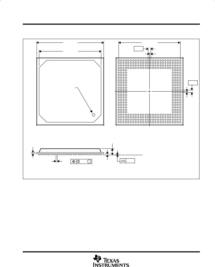
TMS320C6203B
FIXED POINT DIGITAL SIGNAL PROCESSOR
SPRS086K – JANUARY 1999 – REVISED APRIL 2003
MECHANICAL DATA
GNZ (S–PBGA–N352) |
|
|
|
|
|
|
|
|
|
|
|
PLASTIC BALL GRID ARRAY |
|||||||||||
27,20 |
|
|
|
|
|
|
|
|
25,00 TYP |
|
|
|
|
|
|
|
|
|
|
||||
SQ |
|
|
|
|
|
|
|
|
|
|
|
|
|
|
|
|
|
|
|||||
26,80 |
|
|
|
|
|
|
|
|
|
|
|
|
|
|
|
|
|
|
|
|
|
|
|
25,20 |
|
|
|
|
|
|
1,00 |
|
|
|
|
|
|
|
|
|
|
|
|
|
|
|
|
|
|
|
|
|
|
|
|
|
|
|
|
|
|
|
|
|
|
|
|
|
|
|
|
24,80 SQ |
|
|
|
|
|
|
|
|
|
|
|
|
|
0,50 |
|
|
|
|
|
|
|
||
|
|
|
AF |
|
|
|
|
|
|
|
|
|
|
|
|
|
|
|
|
|
|
|
|
|
|
|
AE |
|
|
|
|
|
|
|
|
|
|
|
|
|
|
|
|
|
|
|
|
|
|
|
AD |
|
|
|
|
|
|
|
|
|
|
|
|
|
|
|
|
|
|
|
|
|
|
|
AC |
|
|
|
|
|
|
|
|
|
|
|
|
|
|
|
|
|
|
|
|
|
|
|
AB |
|
|
|
|
|
|
|
|
|
|
|
|
|
|
|
|
|
|
|
|
|
|
|
AA |
|
|
|
|
|
|
|
|
|
|
|
|
|
|
|
|
|
|
|
|
|
|
|
Y |
|
|
|
|
|
|
|
|
|
|
|
|
|
|
|
|
|
|
|
|
|
|
|
W |
|
|
|
|
|
|
|
|
|
|
|
|
|
|
|
|
|
|
|
|
|
|
|
V |
|
|
|
|
|
|
|
|
|
|
|
|
|
|
|
|
|
|
|
1,00 |
|
|
|
U |
|
|
|
|
|
|
|
|
|
|
|
|
|
|
|
|
|
|
|
|
A1 Corner |
|
|
T |
|
|
|
|
|
|
|
|
|
|
|
|
|
|
|
|
|
|
|
|
|
|
R |
|
|
|
|
|
|
|
|
|
|
|
|
|
|
|
|
|
|
|
|
|
|
|
|
P |
|
|
|
|
|
|
|
|
|
|
|
|
|
|
|
|
|
|
|
|
|
|
|
N |
|
|
|
|
|
|
|
|
|
|
|
|
|
|
|
|
|
|
|
|
|
|
|
M |
|
|
|
|
|
|
|
|
|
|
|
|
|
|
|
|
|
|
|
|
|
|
|
L |
|
|
|
|
|
|
|
|
|
|
|
|
|
|
|
|
|
|
|
0,50 |
|
|
|
K |
|
|
|
|
|
|
|
|
|
|
|
|
|
|
|
|
|
|
|
|
|
|
|
J |
|
|
|
|
|
|
|
|
|
|
|
|
|
|
|
|
|
|
|
|
|
|
|
H |
|
|
|
|
|
|
|
|
|
|
|
|
|
|
|
|
|
|
|
|
|
|
|
G |
|
|
|
|
|
|
|
|
|
|
|
|
|
|
|
|
|
|
|
|
|
|
|
F |
|
|
|
|
|
|
|
|
|
|
|
|
|
|
|
|
|
|
|
|
|
|
|
E |
|
|
|
|
|
|
|
|
|
|
|
|
|
|
|
|
|
|
|
|
|
|
|
D |
|
|
|
|
|
|
|
|
|
|
|
|
|
|
|
|
|
|
|
|
|
|
|
C |
|
|
|
|
|
|
|
|
|
|
|
|
|
|
|
|
|
|
|
|
|
|
|
B |
|
|
|
|
|
|
|
|
|
|
|
|
|
|
|
|
|
|
|
|
|
|
|
A |
|
|
|
|
|
|
|
|
|
|
|
|
|
|
|
|
|
|
|
|
|
|
|
1 |
3 |
5 |
7 |
|
9 |
11 |
13 |
15 |
17 |
19 |
21 |
23 |
25 |
|||||||
|
|
|
2 |
4 |
6 |
|
8 |
10 |
12 |
14 |
16 |
18 |
20 |
22 |
24 |
26 |
|||||||
|
|
|
|
|
|
|
|
|
Bottom View |
|
|
|
|
|
|
|
|
||||||
|
|
|
2,80 MAX |
|
|
|
|
|
|
|
|
|
|
|
|
|
|
|
|
|
|
|
|
0,50 NOM |
|
|
|
|
|
|
|
|
|
|
|
|
|
|
|
|
|
|
|
|
|
|
|
|
|
|
|
Seating Plane |
|
|
|
|
|
|
|
|
|
|
|
|
|
|
|
||||
0,70 |
0,10 |
M |
0,60 |
|
0,15 |
|
|
|
|
|
|
|
|
|
|
|
|
|
|
|
|
|
|
0,50 |
|
|
|
|
|
|
|
|
|
|
|
|
|
|
|
|
|
|
|
||||
|
|
|
|
|
|
|
|
|
|
|
|
|
|
|
|
|
|
|
|
||||
|
|
|
|
|
|
|
|
|
|
|
|
|
|
|
|
|
|
|
|
|
|
||
|
|
0,40 |
|
|
|
|
|
|
|
|
|
|
|
|
|
|
|
|
|
|
|
|
|
|
|
|
|
|
|
|
|
|
|
|
|
|
|
|
|
|
|
|
|
|
|
|
|
|
|
|
|
|
|
|
|
|
|
|
|
|
|
|
|
|
|
|
|
|
4202595-2/E 12/02 |
||
NOTES: A. All linear dimensions are in millimeters.
B.This drawing is subject to change without notice.
C.Flip chip application only.
D.Substrate color may vary.
thermal resistance characteristics (S-PBGA package)
NO |
|
|
|
° C/W |
Air Flow m/s† |
1 |
RΘ |
JC |
Junction-to-case |
6.35 |
N/A |
2 |
RΘ |
JA |
Junction-to-free air |
20.0 |
0.00 |
3 |
RΘ |
JA |
Junction-to-free air |
17.0 |
0.50 |
4 |
RΘ |
JA |
Junction-to-free air |
16.3 |
1.00 |
5 |
RΘ |
JA |
Junction-to-free air |
15.2 |
2.00 |
† m/s = meters per second
POST OFFICE BOX 1443 • HOUSTON, TEXAS 77251–1443 |
97 |

TMS320C6203B
FIXED POINT DIGITAL SIGNAL PROCESSOR
SPRS086K – JANUARY 1999 – REVISED APRIL 2003
MECHANICAL DATA
GLS (S-PBGA-N384) |
PLASTIC BALL GRID ARRAY |
18,10 |
SQ |
|
|
|
|
|
16,80 TYP |
|
|
|
|
|
|
|
|
||||
17,90 |
|
|
|
|
0,80 |
|
|
|
|
|
|
|
|
||||||
|
|
|
|
|
|
|
|
|
|
|
|
|
|
|
|
|
|
|
|
|
|
|
|
|
|
|
|
|
|
|
|
0,40 |
|
|
|
|
|
|
|
|
|
|
AB |
|
|
|
|
|
|
|
|
|
|
|
|
|
|
|
|
|
|
|
AA |
|
|
|
|
|
|
|
|
|
|
|
|
|
|
|
|
|
|
|
Y |
|
|
|
|
|
|
|
|
|
|
|
|
|
|
|
|
|
|
|
W |
|
|
|
|
|
|
|
|
|
|
|
|
|
|
|
|
|
|
|
V |
|
|
|
|
|
|
|
|
|
|
|
|
|
|
|
|
|
|
|
U |
|
|
|
|
|
|
|
|
|
|
|
|
|
|
|
0,80 |
|
|
|
T |
|
|
|
|
|
|
|
|
|
|
|
|
|
|
|
|
|
|
|
R |
|
|
|
|
|
|
|
|
|
|
|
|
|
|
|
|
|
|
|
P |
|
|
|
|
|
|
|
|
|
|
|
|
|
|
|
|
|
|
|
N |
|
|
|
|
|
|
|
|
|
|
|
|
|
|
|
|
A1 Corner |
|
M |
|
|
|
|
|
|
|
|
|
|
|
|
|
|
|
|
|
|
|
|
L |
|
|
|
|
|
|
|
|
|
|
|
|
|
|
|
|
|
|
|
K |
|
|
|
|
|
|
|
|
|
|
|
|
|
|
|
|
|
|
|
J |
|
|
|
|
|
|
|
|
|
|
|
|
|
|
|
0,40 |
|
|
|
H |
|
|
|
|
|
|
|
|
|
|
|
|
|
|
|
|
|
|
|
G |
|
|
|
|
|
|
|
|
|
|
|
|
|
|
|
|
|
|
|
F |
|
|
|
|
|
|
|
|
|
|
|
|
|
|
|
|
|
|
|
E |
|
|
|
|
|
|
|
|
|
|
|
|
|
|
|
|
|
|
|
D |
|
|
|
|
|
|
|
|
|
|
|
|
|
|
|
|
|
|
|
C |
|
|
|
|
|
|
|
|
|
|
|
|
|
|
|
|
|
|
|
B |
|
|
|
|
|
|
|
|
|
|
|
|
|
|
|
|
|
|
|
A |
|
|
|
|
|
|
|
|
|
|
|
|
|
|
|
|
|
|
|
1 |
3 |
5 |
7 |
9 |
11 |
13 |
15 |
17 |
19 |
21 |
||||||
|
|
|
2 |
4 |
6 |
8 |
|
10 |
12 |
14 |
16 |
18 |
20 |
22 |
|||||
Heat Slug |
|
|
|
|
|
Bottom View |
|
|
|
|
|
|
|
||||||
1,00 NOM |
|
|
2,80 MAX |
|
|
|
|
|
|
|
|
|
|
|
|
|
|
|
|
|
|
|
|
|
|
|
|
|
|
|
|
|
|
|
|
|
|
|
|
|
|
|
Seating Plane |
|
|
|
|
|
|
|
|
|
|
|
|
|
|||
0,55 |
0,10 |
M |
0,45 |
0,12 |
|
|
|
|
|
|
|
|
|
|
|
|
|
|
|
0,45 |
|
|
|
|
|
|
|
|
|
|
|
|
|
|
|
||||
|
|
|
|
|
|
|
|
|
|
|
|
|
|
|
|
|
|
||
|
|
|
0,35 |
|
|
|
|
|
|
|
|
|
|
|
|
|
|
|
|
|
|
|
|
|
|
|
|
|
|
|
|
|
|
|
|
4188959-3/E 11/01 |
|||
NOTES: A. All linear dimensions are in millimeters.
B.This drawing is subject to change without notice.
C.Thermally enhanced plastic package with heat slug (HSL)
D.Flip chip application only
thermal resistance characteristics (S-PBGA package)
NO |
|
|
|
° C/W |
Air Flow m/s† |
1 |
RΘ |
JC |
Junction-to-case |
0.85 |
N/A |
2 |
RΘ |
JA |
Junction-to-free air |
21.6 |
0.0 |
3 |
RΘ |
JA |
Junction-to-free air |
18.0 |
0.5 |
4 |
RΘ |
JA |
Junction-to-free air |
15.5 |
1.0 |
5 |
RΘ |
JA |
Junction-to-free air |
12.8 |
2.0 |
† m/s = meters per second
98 |
POST OFFICE BOX 1443 • HOUSTON, TEXAS 77251–1443 |

TMS320C6203B
FIXED POINT DIGITAL SIGNAL PROCESSOR
SPRS086K – JANUARY 1999 – REVISED APRIL 2003
MECHANICAL DATA
GNY (S-PBGA-N384) |
PLASTIC BALL GRID ARRAY |
18,10 |
SQ |
|
|
|
|
|
|
16,80 TYP |
|
|
|
|
|
|
|
||||
17,90 |
|
|
|
|
|
0,80 |
|
|
|
|
|
|
|
||||||
|
|
|
|
|
|
|
|
|
|
|
|
|
|
|
|
|
|
|
|
|
|
|
|
|
|
|
|
|
|
|
|
|
0,40 |
|
|
|
|
|
|
|
|
|
|
AB |
|
|
|
|
|
|
|
|
|
|
|
|
|
|
|
|
|
|
|
AA |
|
|
|
|
|
|
|
|
|
|
|
|
|
|
|
|
|
|
|
Y |
|
|
|
|
|
|
|
|
|
|
|
|
|
|
|
|
|
|
|
W |
|
|
|
|
|
|
|
|
|
|
|
|
|
|
|
|
|
|
|
V |
|
|
|
|
|
|
|
|
|
|
|
|
|
|
|
|
|
|
|
U |
|
|
|
|
|
|
|
|
|
|
|
|
|
|
0,80 |
|
|
|
|
T |
|
|
|
|
|
|
|
|
|
|
|
|
|
|
|
|
|
|
|
R |
|
|
|
|
|
|
|
|
|
|
|
|
|
|
|
|
|
|
|
P |
|
|
|
|
|
|
|
|
|
|
|
|
|
|
|
|
|
|
|
N |
|
|
|
|
|
|
|
|
|
|
|
|
|
|
|
|
|
|
|
M |
|
|
|
|
|
|
|
|
|
|
|
|
|
|
|
A1 Corner |
|
|
L |
|
|
|
|
|
|
|
|
|
|
|
|
|
|
|
|
|
|
K |
|
|
|
|
|
|
|
|
|
|
|
|
|
|
|
||
|
|
|
|
J |
|
|
|
|
|
|
|
|
|
|
|
|
|
|
0,40 |
|
|
|
|
H |
|
|
|
|
|
|
|
|
|
|
|
|
|
|
|
|
|
|
|
G |
|
|
|
|
|
|
|
|
|
|
|
|
|
|
|
|
|
|
|
|
|
|
|
|
|
|
|
|
|
|
|
|
|
|
|
|
|
|
|
F |
|
|
|
|
|
|
|
|
|
|
|
|
|
|
|
|
|
|
|
E |
|
|
|
|
|
|
|
|
|
|
|
|
|
|
|
|
|
|
|
D |
|
|
|
|
|
|
|
|
|
|
|
|
|
|
|
|
|
|
|
C |
|
|
|
|
|
|
|
|
|
|
|
|
|
|
|
|
|
|
|
B |
|
|
|
|
|
|
|
|
|
|
|
|
|
|
|
|
|
|
|
A |
|
|
|
|
|
|
|
|
|
|
|
|
|
|
|
|
|
|
|
1 |
3 |
5 |
7 |
9 |
11 |
13 |
15 |
17 |
19 |
21 |
|||||
|
|
|
|
2 |
4 |
6 |
8 |
|
10 |
12 |
14 |
16 |
18 |
20 |
22 |
||||
|
|
|
|
|
|
|
|
Bottom View |
|
|
|
|
|
|
|||||
|
|
|
|
2,35 MAX |
|
|
|
|
|
|
|
|
|
|
|
|
|
|
|
|
|
|
|
Seating Plane |
|
|
|
|
|
|
|
|
|
|
|
|
|||
0,55 |
|
0,10 |
M |
0,45 |
0,12 |
|
|
|
|
|
|
|
|
|
|
|
|
|
|
0,45 |
|
|
|
|
|
|
|
|
|
|
|
|
|
|
|||||
|
|
|
|
|
|
|
|
|
|
|
|
|
|
4201137/C 11/01 |
|||||
|
|
|
|
0,35 |
|
|
|
|
|
|
|
|
|
|
|
||||
NOTES: A. All linear dimensions are in millimeters.
B.This drawing is subject to change without notice.
C.Flip chip application only
D.Substrate color may vary
thermal resistance characteristics (S-PBGA package)
NO |
|
|
|
C6203B |
Air Flow m/s† |
|
|
|
(° C/W) |
||
|
|
|
|
|
|
|
|
|
|
|
|
1 |
RΘ |
JC |
Junction-to-case |
6.27 |
N/A |
2 |
RΘ |
JA |
Junction-to-free air |
17.6 |
0.0 |
3 |
RΘ |
JA |
Junction-to-free air |
13.9 |
0.5 |
4 |
RΘ |
JA |
Junction-to-free air |
13.1 |
1.0 |
5 |
RΘ |
JA |
Junction-to-free air |
11.9 |
2.0 |
† m/s = meters per second
POST OFFICE BOX 1443 • HOUSTON, TEXAS 77251–1443 |
99 |