


 MTC
MTC
Anchor Handling Course
Hydraulic winches
General remarks
There is little difference in running a hydraulic winch and an electrical winch. The winch is operated with handles for heave in and pay out and for controlling the speed.
The lay out of the winch configuration can vary according to ship’s type. Some ships are equipped with 2 towing winches and 2 anchor handling winches. (P type)
Latest deliveries (B-type) with hydraulic winches have 1 anchor handling winch and 2 towing winches.
Both types have chain wheels installed on the towing winches.
Lay out (B-type)
The winch is “waterfall type” and consists of 1 anchor handling winch and 2 towing winches. For running the winches 4 big hydraulic pumps are installed in a pump room. They supply hydraulic oil to 8 hydraulic motors. The motors transfer power to close clutches which again transfer the power to a drive shaft. The drive shaft is common for the towing winches.
The anchor-handling winch is not clutch able but is clutched in permanently. It is possible to route the hydraulic oil round the anchor-handling winch by remote controlled switches on the control panel. The winch has 4 gearboxes. 2 gearboxes for the anchor handling winch and 1 for each of the towing winches.
Clutch arrangement
In order to clutch and de-clutch winch-drums a power pack is installed to supply all clutches.
The following options exist for clutching. Either the anchor-handling drum or a towing drum. 2 winches can be clutched at the same time.
“High speed” or “low speed” clutching is not an option as one some ships.
Clutching is done at the panel on the bridge. From there clutching and de-clutching is done as well as choosing routing of the hydraulic oil for either anchor handling winch or towing winches.
Before clutching the brake must be “ON”. A passive surveillance will warn if trying to perform an illegal act.
M:\ANCHOR HANDLING\Course Material\Training Manual New\Chapter 05\AHT winches.doc
Chapter 05 |
Page 9 |

 MTC
MTC
Anchor Handling Course
Brake arrangement
The hydraulic winch has 2 braking arrangements. The hydraulic brake acts via the motors and the mechanical band brake, which is manually operated.
The hydraulic brake is activated when the oil is passing discs in the motors. A certain slippage will. Always exist in the hydraulic motors giving a slight rotation with tension on the wire. It is therefore quite normal to observe the winch paying out slightly even though the handle is not activated.
If the operation demands the wire to be 100 % secured it is necessary to put the band brake “ON”.
Tension control
The maximum tension, which can be applied to the wire/chain, depends on the pressure in the main hydraulic system.
This can be adjusted by a potentiometer installed in the control panel for each winch. If the tension raises to a higher value than the adjusted, the winch will pay out.
This is very useful when chasing for an anchor, as it can avoid breakage of chaser collar and
PCP.
Emergency release and ultimate release
When the emergency release button is pushed, the band brake is lifted and the pressure in the hydraulic system is reduced to a minimum, causing the winch to pay out. The normal over speed protection is active.
If a winch drum which is not connected to a motor is emergency released, a small brake force will be applied by the band brake, just enough to prevent the wire from jamming on the drum.
The ultimate release button has the same function, the only difference is that the over speed protection system is not active. This might lead to serious damage of the winch motors.
M:\ANCHOR HANDLING\Course Material\Training Manual New\Chapter 05\AHT winches.doc
Chapter 05 |
Page 10 |
 MTC
MTC
Anchor Handling Course
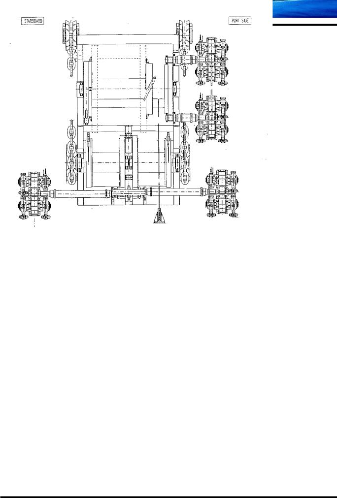
Hydraulic winch, “B-type”
M:\ANCHOR HANDLING\Course Material\Training Manual New\Chapter 05\AHT winches.doc
Chapter 05 |
Page 11 |