


 MTC
MTC
Anchor Handling Course
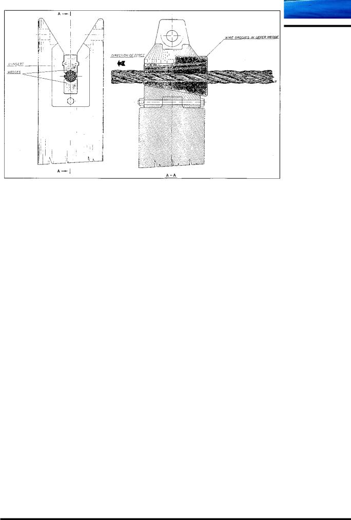
KARM FORK Shark Jaw
Wire and chain Stopper
Fig 1
M:\ANCHOR HANDLING\Course Material\Training Manual New\Chapter 07\6.0 Karm Fork.doc
Chapter 07
 MTC
MTC
Anchor Handling Course
Inserts for KARM FORK
Fig 2
Inserts and Carpenter Stoppers for KARM FORK
Fig 3
M:\ANCHOR HANDLING\Course Material\Training Manual New\Chapter 07\6.0 Karm Fork.doc
Chapter 07

Maersk Training Centre A/S
Karm Fork in top position with top cover on. Towing Pins in parked position.
Looking aft.
Karm Fork Shark Jaw System
Anchor Handling Course, chapter 7

Maersk Training Centre A/S
Karm Fork and Towing Pin in top position.
Looking aft.
MAERSK DISPATCHER
Karm Fork Shark Jaw System
Anchor Handling Course, chapter 7

Maersk Training Centre A/S
Karm Forks and Towing Pins in top position with Safety Pins in.
Looking towards port.
Karm Fork Shark Jaw System
Anchor Handling Course, chapter 7

Maersk Training Centre A/S
Karm Forks and Towing Pins in top position with Safety Pins in.
Chain stopped off in both sides. Looking aft.
Karm Fork Shark Jaw System
Anchor Handling Course, chapter 7

Maersk Training Centre A/S
Both sets of Towing Pins in up / locked position. Both sets of Karm Forks in parked position, ready for use. Looking aft.
Karm Fork Shark Jaw System
Anchor Handling Course, chapter 7

 MTC
MTC
Anchor Handling Course
“Good Advises and Guidelines” in use of NON rotation-resistant steel wires.
First of all it is recommended to read the Technical Information regarding steel wires by Fyns Kran Udstyr / Randers Reb. These information make the foundation for the following “Good
Advises and Guidelines”.
The wire-thread, which is used in the production of a steel wire, has a very high tensile strength compared by ordinary steel.
Trade steel (“Steel 37”) has a tensile strength at app. 37 kp/mm2 (362 N/mm2)
Wire steel has a tensile strength from app. 140 to 220 kp/mm2 (1370 – 2160 N/mm2)
The fact that the wire-thread is so strong has the disadvantage that the bending strength will be reduced. The wire-thread breaks easily, if it is bent – especially under the circumstances as a “Work wire” is working under.
Below different subjects concerning or are used in connection with steel wire will be covered.
Especially the negative influence on the steel wire will be covered.
Swivel: The breaking load will locally be reduced by app. 30%
When a steel wire is under load it opens and at the same time it will be extended. The swivel “makes” it easier for the wire to open, stress failure will occur and the life expectancy will be reduced.
Working Load: A steel wire must maximum be loaded with 50% of the breaking load.
The material reaches the yield point at 50% of the breaking load. The wirethreads get stiff and will break when they are bent. The life expectancy will be reduced.
If the load constantly is about the 50%, the steel wire will break.
Loops / kinks: Gives a reduction in the breaking load at app. 50%
The steel wire will be heavily deformed, when e.g. a kink is straightened out by applying of a load.
A kink is formed due to extraction of a loop.
Fleet angle: Does not matter on ships with spooling devices.
But the steel wire has to run straight into a block.
Running in Steel Wire Rope:
Is recommended, if time. In this way the steel wire will gradually become accustomed to the new conditions.
M:\ANCHOR HANDLING\Course Material\Training Manual New\Chapter 08\1.0 Wire 2001.11.UK.doc
Chapter 8 / 1 |
Page 1 |
 MTC
MTC
Anchor Handling Course
Fitting to Drum: Fundamentally you ought to follow the recommendations made by the manufacturer.
But this does only matter with the first layer of steel wire. It doesn’t matter on drums with several layers of steel wire.
If it isn’t possible to fit the steel wire at the right side due to the construction of the drum, you must subsequent keep away from the first layer on the drum.
Spooling: Care must be taken to ensure that the reel and the drum are running in the same direction. That means from under-turn to under-turn and from overturn to over-turn. If this isn’t done correctly, the steel wire is subjected to torsion.
In order to achieve problem-free spooling on multi-layer drums it is extremely important that the steel wire is spooled on with tension. If the layers are too loose; the upper layers can damage or cut into the layers below when tension is applied, resulting in damage to the steel wire.
Spooling from drum to reel: All tension / torsion must first be released by deploying the wire into the water – at sufficient water depth – before the steel wire is spooled on to the reel.
The best-recommended way of doing this transferring; is first to deploy the steel wire into the water, secure it in the Shark Jaws and afterwards spool the steel wire directly from the water onto the reel.
It is of course a demand, that the reel is able to lift the weight of the deployed steel wire.
Bending around a mandrel: (Can be compared with a U-lift.)
When the steel wire “works” on the stern roller or is spooled on the drum this is “Bending around a mandrel”. How big / small this proportion is, depends on the diameter of the “drum” (Winch drum, stern roller, guide pins) and the diameter of the wire which is supposed to “work” on the drum.
Depending on the proportion between mandrel diameter and steel wire diameter, reduction in the breaking load will be:
(d = diameter of the steel wire)
Mandrel, diam.: |
Breaking load, reduced: |
40 d |
5% |
15 d |
10% |
5 d |
20% |
4 d |
25% |
3 d |
30% |
2 d |
40% |
1 d |
50% |
M:\ANCHOR HANDLING\Course Material\Training Manual New\Chapter 08\1.0 Wire 2001.11.UK.doc
Chapter 8 / 1 |
Page 2 |