- •Introduction to the Anchor Handling Course
- •Technical Specifications:
- •Winch Layout:
- •Power Settings / Bollard Pull
- •All operations on board must be performed in accordance with Company Procedures.
- •Risk Assessment
- •Planning
- •Planning:
- •Goal, example:
- •What to do:
- •Electrical winches
- •Winch operation
- •General Arrangement
- •A/H-Drum at full Capacity
- •Over speed
- •Water brake
- •Band brake
- •QUICK & Full Release
- •Hydraulic Winches
- •Lay out (B-type)
- •Hydraulic winch, “B-type”
- •TOWCON
- •Instruction for use of Wire Drums
- •Changing of Chain Wheels (Wildcats / Chain Lifter)
- •TRIPLEX - SHARK JAW SYSTEM.
- •Operation
- •Maintenance and inspections
- •Safety
- •2. OPERATION:
- •QUICK RELEASE:
- •EMERGENCY RELEASE:
- •CONTROL PANEL
- •Marks for Locked on Hinge Link
- •2.2- OPERATION OF THE "JAW IN POSITION ACCEPT" LEVER:
- •2.3 OPERATION OF THE CONTROL PANEL AT EMERGENCY POWER.
- •3. ELECTRIC AND HYDRAULIC POWER SYSTEM.
- •3. 1. ARRANGEMENT OF SYSTEM.
- •3.2. FUNCTIONING OF QUICK RELEASE - JAWS ONLY.
- •3.3. FUNCTIONING OF EMERGENCY RELEASE
- •4.2 Test without Load.
- •4.3 Test with Load.
- •5. General Maintenance
- •5.1 Accumulators Depressurising
- •5.2 Shark Jaw Unit
- •5.3 Guide Pins Units
- •5.4 Hydraulic System
- •5.5 Electric System
- •6. Control Measurements / Adjustments.
- •6.2 Adjustment of inductive proximity switches on lock cylinders.
- •6.3 Adjustment of Pressure Switches for Lock Pressure.
- •7. Test Program – Periodical Control
- •7.2 Checking List – Periodic Control Mechanical / Hydraulic.
- •7.3 Checking List – Periodic Control Electrical
- •7.4 Testing without Load – Yearly Testing.
- •7.5 Load Test – Emergency Release – 5 Year Control.
- •“Mark on line !”
- •“Double set of Jaws, Pins and Wire lifter”
- •View from the bridge.
- •“JAW READY FOR OPERATION”
- •“JAW LOCK POSITION ACCEPTED”
- •KARM FORK – SHARK JAW SYSTEM.
- •Wire and chain Stopper
- •Inserts for KARM FORK
- •Martensite:
- •Recommendations:
- •1. THE BASIC ELEMENTS OF STEEL WIRE ROPE
- •2. STEEL WIRE ROPE CONSTRUCTIONS
- •3. SPECIAL STEEL WIRE ROPES
- •4. USE OF STEEL WIRE ROPE
- •5. SELECTING THE RIGHT STEEL WIRE ROPE
- •6. ORDERING STEEL WIRE ROPE
- •7. STEEL WIRE ROPE TOLERANCES
- •8. HANDLING, INSPECTION AND INSTALLATION
- •9. INSPECTION AND MAINTENANCE
- •10. ELONGATION AND PRE-STRETCHING
- •11. OPERATING TEMPERATURES
- •12. MARTENSITE FORMATION
- •13. END TERMINATIONS
- •14. SOCKETING (WIRELOCK)
- •15. DRUM CAPACITY
- •16. CLASSIFICATION AND USE OF STEEL WIRE ROPE
- •17. ROPES
- •18. CHAINS AND LIFTING COMPONENTS
- •19. TECHNICAL CONVERSION TABLES
- •SWIVEL
- •MoorLink Swivel
- •Pin Extractor
- •Socket Bench
- •Chains and Fittings
- •STUD LINK MOORING CHAIN
- •OPEN LINK MOORING CHAIN
- •KENTER JOINING LINKS
- •PEAR SHAPE ANCHOR CONNECTING LINK
- •DETACHABLE CONNECTING LINK
- •D’ TYPE JOINING SHACKLES
- •‘D’ TYPE ANCHOR SHACKLES
- •SHACKLES
- •JAW & JAW SWIVELS
- •BOW & EYE SWIVELS
- •MOORING RINGS
- •FISH PLATES
- •PELICAN HOOKS
- •SLIP HOOKS
- •‘J’ CHASERS
- •PERMANENT CHASERS
- •DETACHABLE PERMANENT CHAIN CHASERS
- •PERMANENT WIRE CHASERS
- •‘J’ LOCK CHAIN CHASERS
- •The way to break the anchor loose of the bottom is therefore:
- •Table of contents
- •Introduction
- •General
- •Mooring systems
- •Mooring components
- •History of drag embedment anchors
- •Characteristics of anchor types
- •History of vryhof anchor designs
- •Criteria for anchor holding capacity
- •Theory
- •Criteria for good anchor design
- •Aspects of soil mechanics in anchor design
- •Soil classification
- •Fluke/shank angle
- •Fluke area
- •Strength of an anchor design
- •Anchor loads and safety factors
- •Anchor behaviour in the soil
- •Proof loads for high holding power anchors
- •Anchor tests
- •Soil table
- •Practice
- •Introduction
- •Soil survey
- •Pile or anchor
- •Setting the fluke/shank angle
- •Connecting a swivel to the Stevpris anchor
- •Chasers
- •Chaser types
- •Stevpris installation
- •Laying anchors
- •Retrieving anchors
- •Anchor orientation
- •Decking the Stevpris anchor
- •What not to do!
- •Racking the Stevpris
- •Deploying Stevpris from the anchor rack
- •Boarding the anchor in deep water
- •Ballast In fluke
- •Chaser equilibrium
- •Deployment for permanent moorings
- •Piggy-backing
- •Piggy-back methods
- •Stevmanta VLA installation
- •Installation procedure
- •Stevmanta retrieval
- •Double line installation procedure
- •Stevmanta retrieval
- •Double line installation with Stevtensioner
- •The Stevtensioner
- •The working principle of the tensioner
- •Measurement of the tensions applied
- •Umbilical cable and measuring pin
- •Break - link
- •Duration of pretensioning anchors and piles
- •Handling the Stevtensioner
- •General tensioning procedures
- •Hook-up
- •Lowering
- •Tensioning mode
- •Retrieving
- •Supply vessels/anchor handling vessels
- •Product data
- •Introduction
- •Dimensions of vryhof anchor types
- •Proof load test for HHP anchors (US units)
- •Dimensions of vryhof tensioners
- •Proof load/break load of chains (in US units)
- •Chain components and forerunners
- •Connecting links
- •Conversion table
- •Mooring line catenary
- •Mooring line holding capacity
- •Shackles
- •Wire Rope
- •Wire rope sockets
- •Thimbles
- •Synthetic ropes
- •Mooring hawsers
- •Main dimensions chasers
- •Stevin Mk3 UHC chart
- •Stevin Mk3 drag and penetration chart
- •Stevpris Mk5 UHC chart
- •Stevpris Mk5 drag and penetration chart
- •Stevmanta VLA UPC chart
- •Introduction
- •Propulsion system
- •Propellers
- •Thrusters
- •Rudders
- •Manoeuvring
- •Current
- •Wind
- •Other forces
- •Turning point (Pivot point)
- •Ship handling
- •General layout Jack-Up drilling unit:
- •General information about a Semi Submersible drilling unit:
MTC
Anchor Handling Course
Electrical winches
The winches mentioned are based on A-type winches.
The winches are of waterfall type.
Electrical winches are driven via shaft generator or harbour generators through main switchboard to electronic panel to DC motors.
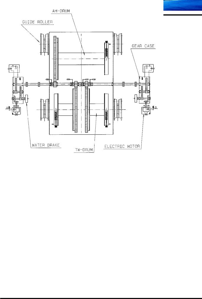
The winch lay out is with anchor handling drum on top and 2 towing winches underneath and forward of the A/H winch. The towing winches each has a chain wheel interchangeable according to required size.
The winch has 4 electrical motors. The motors can be utilised with either 2 motors or all 4 motors for the AH drum depending on required tension or with one or two motors for the towing drums. The coupling of motors is via clutches and pinion drive.
The clutching and de-clutching of drums is done with hydraulic clutches driven by a power pack. This power pack is also used for the brake system on the drums, as the band brake is always
“on” when the handle is not activated.
Apart from the band brake there is also a water brake for each electric motor as well as a disc brake. The disc brake is positioned between the electric motor and the gearbox. The water brake is connected to the gearbox and within normal working range, 50% of the brake force is from the water brake and 50% from the electric motor brake.
The drums are driven via pinion shafts clutch able to pinion drives on the drums. Pinion drives are lubricated continuously by a central lubricating system to ensure a good lubrication throughout the service. The control handle for the winch activates the lubrication system, and only the active pinions are lubricated.
Each winch also has a “spooling device” to ensure a proper and equal spooling of wire on the drum. The spooling device is operated by means of a hydraulic system supplied from the same power pack as mentioned above.
Finally, separating the winch area and the main deck is the “crucifix” which divides the work wires in compartments for each winch. It is also part of the winch garage construction.
M:\ANCHOR HANDLING\Course Material\Training Manual New\Chapter 05\AHT winches.doc
Chapter 05 |
Page 1 |
MTC
Anchor Handling Course
Winch operation
The winches are operated from the aft desks in port side, but can also be operated at the winch. When operated locally from the winch only ½ speed can be obtained. There are different bridge lay outs but they are all to some degree based on previous design and partly identical.
To ensure a good overview for the operator a SCADA system has been installed showing the winch status. Further there is a clutch panel allowing the operator to clutch drums in and out according to requirement. On the panel lub oil pumps for gearboxes, pumps for hydraulic system and grease pump for gearwheels are started.
Winch configuration and adjustment is done on the panel, which here at Maersk Training Centre is illustrated by a “touch screen” monitor. The different settings can be done on the “touch screen”.
Normally the winch drums are not visible from the bridge. Instead the drums are monitored via different selectable cameras installed in the winch garage. These are connected to monitors on the aft bridge allowing the operator and the navigator to monitor the drums.
M:\ANCHOR HANDLING\Course Material\Training Manual New\Chapter 05\AHT winches.doc
Chapter 05 |
Page 2 |
MTC
Anchor Handling Course
General Arrangement
M:\ANCHOR HANDLING\Course Material\Training Manual New\Chapter 05\AHT winches.doc
Chapter 05 |
Page 3 |
MTC
Anchor Handling Course
A/H-Drum at full Capacity
M:\ANCHOR HANDLING\Course Material\Training Manual New\Chapter 05\AHT winches.doc
Chapter 05 |
Page 4 |
MTC
Anchor Handling Course
SCADA: Supervisory Control and Data Acquisition
This system gives the operator an overview of the winch status as well as a warning/alarm if anything is about to go wrong or already has gone wrong. The system is PLC governed –
“Watchdog”.
3 types of alarms are shown: |
|
Alarm: |
A functional error in the system leads to stop of winch. |
Pre alarm: |
The winch is still operational but an error has occurred, |
|
which can lead to a winch stop/failure if the operation |
|
continues in same mode. |
Warning: |
Operator fault/wrong or illegal operation |
The clutch panel
On the clutch panel the different modes of operation can be chosen. In order to clutch all functions must be “off”. It is not possible to clutch if the drum is rotating or a motor is running. Change of “operation mode” can not be done during operation.
Speed control mode
Motors can be operated with the handle in:
Manual clutch control.
If no drum is clutched in.
When drums have been chosen.
Tension |
|
Static wire tension: |
The pull in wire/chain is measured from the braking load. The drum is |
|
not rotating and the band brake is “ON”. The pull is calculated from |
|
“strain gauges”. |
Dynamic wire tension: |
The pull in the wire/chain is measured from the actual torque in the |
|
motor. The drum is rotating or almost stopped but not braked. |
Max wire tension: |
Highest possible pull in the wire/chain that can be handled by the motor |
|
converted from static pull to dynamic pull. |
M:\ANCHOR HANDLING\Course Material\Training Manual New\Chapter 05\AHT winches.doc
Chapter 05 |
Page 5 |