

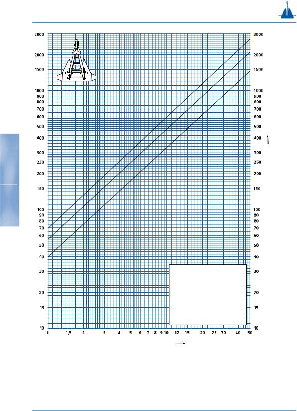
Stevpris Mk5 drag and penetration chart
|
|
|
|
|
|
|
|
|
|
|
|
|
|
|
|
y |
|
|
|
|
|
|
|
|
|
|
|
|
|
|
|
|
|
|
|
|
la |
|
|
|
|
|
|
||
|
|
|
|
|
|
|
|
|
|
|
|
ftc |
|
|
|
|
|
|
|
|
||
|
|
|
|
|
|
|
|
|
ryso |
|
|
|
|
|
|
|
|
|
||||
|
|
|
|
|
|
|
e |
|
|
|
|
|
|
|
|
|
|
|
|
|
||
|
|
|
|
gin |
v |
|
|
|
|
|
|
|
|
|
|
|
|
|
|
|
||
|
|
ra |
|
|
|
|
|
|
|
|
|
|
|
|
|
|
|
|
|
|
||
|
|
d |
|
|
|
|
|
|
|
|
|
|
|
|
|
|
|
|
|
|
|
|
|
|
|
|
|
|
|
|
|
|
|
|
|
|
|
y |
|
|
|
|
|
||
|
|
|
|
|
|
|
|
|
|
|
|
mcla |
|
|
|
|
|
|
||||
|
|
|
|
|
|
|
|
|
|
iu |
|
|
|
|
|
|
|
|
|
|
||
|
|
|
|
|
|
|
|
|
d |
|
|
|
|
|
|
|
|
|
|
|
||
|
|
|
|
gin |
me |
|
|
|
|
|
|
|
|
|
|
|
|
|
||||
|
|
|
a |
|
|
|
|
|
|
|
|
|
|
|
|
|
|
|
|
|
|
|
|
|
dr |
|
|
|
|
|
|
|
|
|
|
|
|
|
|
|
|
|
|
|
|
|
|
|
|
|
|
|
|
|
|
|
|
|
|
|
|
|
|
|
|
y |
|
|
|
|
|
|
|
|
|
|
|
|
|
|
|
|
|
|
|
|
|
a |
|
|
|
|
|
|
|
|
|
|
|
|
|
|
|
n |
|
|
dcl |
|
|
HC) |
||||
|
|
|
|
|
|
|
|
|
|
|
|
ar |
|
|
|
|
||||||
|
|
|
|
|
|
|
|
|
nda |
|
dh |
|
|
|
|
|
|
s (U |
||||
|
|
|
|
|
in |
|
|
|
|
|
|
|
|
|
|
|
||||||
|
|
|
ag |
sa |
|
|
|
|
|
|
|
|
|
|
|
|
||||||
|
|
|
|
|
|
|
|
|
|
|
|
|
|
|
|
|
|
|||||
|
|
dr |
|
|
|
|
|
|
|
|
|
|
|
|
|
|
|
|
|
|
eretm ytiac in apc |
|
|
|
|
|
|
|
|
|
|
|
|
|
|
|
|
|
|
|
|
|
a |
||
|
|
|
|
|
|
|
|
|
|
|
|
|
|
|
|
|
|
ftcl |
y |
|
||
|
|
|
|
|
|
|
|
|
|
|
|
|
|
ryso |
|
|
|
tionraetenpnda gnldiohtemaltiu |
||||
|
|
|
|
|
|
|
|
|
nin |
ve |
|
|
|
|
|
|
|
|||||
|
|
|
|
|
|
|
|
|
|
|
|
|
|
|
|
|
||||||
|
|
|
|
|
|
|
|
o |
|
|
|
|
|
|
|
|
|
|
|
|
|
|
|
|
|
|
|
|
|
ti |
|
|
|
|
|
|
|
|
|
|
|
|
|
|
|
|
|
|
|
|
|
a |
|
|
|
|
|
|
|
|
|
|
|
|
|
|
|
|
|
|
|
|
|
tr |
|
|
|
|
|
|
|
|
|
|
|
|
|
|
|
|
|
|
|
|
|
e |
|
|
|
|
|
|
|
|
|
|
|
|
|
|
|
|
|
|
|
|
|
n |
|
|
|
|
|
|
|
|
|
|
|
|
|
|
|
|
|
|
|
|
|
e |
|
|
|
|
|
|
|
|
|
|
|
|
|
|
|
|
|
|
|
|
|
|
p |
|
|
|
|
|
|
|
|
|
|
|
|
|
|
|
|
|
|
|
|
|
|
|
|
|
|
|
|
|
|
|
|
|
|
|
|
|
|
|
|
|
y |
133 |
|
|
|
|
|
|
|
|
|
|
|
|
|
|
|
|
|
|
|
|
|
|
|
|
|
|
|
|
|
|
|
|
|
|
|
|
|
|
|
ium |
cla |
|
||||
|
|
|
|
|
|
|
|
|
|
|
|
|
|
ed |
|
|
|
|
|
|
||
|
|
|
|
|
|
|
ion |
in |
m |
|
|
|
|
|
|
|
|
|||||
|
|
|
|
|
|
|
|
|
|
|
|
|
|
|
|
|
||||||
|
|
|
|
|
|
|
|
|
|
|
|
|
|
|
|
|
|
|
||||
|
|
|
|
|
|
rat |
|
|
|
|
|
|
|
|
|
|
|
|
|
|
gradlcatypi toddeoalrhoc |
|
|
|
|
net |
|
|
n |
|
|
|
|
|
|
|
|
|
|
|
|||||
|
|
e |
|
|
|
|
|
|
|
|
|
|
|
|
|
|
|
|
||||
|
|
p |
|
|
|
|
|
|
|
|
|
|
|
|
|
|
|
|
|
|
|
|
|
|
|
|
|
|
|
|
|
|
|
|
|
|
|
|
|
|
|
|
|
ay |
|
|
|
|
|
|
|
|
|
|
|
|
|
|
|
|
|
|
|
|
|
|
rdcl |
|
|
|
|
|
|
|
|
|
|
|
|
|
|
|
|
|
|
|
ndha |
|
|||
|
|
|
|
|
|
|
|
|
|
|
|
|
|
|
da |
|
|
|
|
|||
|
|
|
|
|
|
|
|
|
|
|
|
|
|
n |
|
|
|
|
|
|
|
|
|
|
|
|
|
|
|
io |
|
in |
sa |
|
|
|
|
|
|
|
|
||||
|
|
|
|
|
|
|
|
|
|
|
|
|
|
|
|
|
|
|||||
|
|
|
|
|
|
|
|
|
|
|
|
|
|
|
|
|
|
|
|
|||
|
|
|
|
|
|
at |
|
|
|
|
|
|
|
|
|
|
|
|
|
|
an |
|
|
|
|
|
|
tr |
|
|
|
|
|
|
|
|
|
|
|
|
|
|
|
||
|
|
|
ne |
|
|
|
|
|
|
|
|
|
|
|
|
|
|
|
|
|||
|
|
e |
|
|
|
|
|
|
|
|
|
|
|
|
|
|
|
|
|
|
|
|
|
|
p |
|
|
|
|
|
|
|
|
|
|
|
|
|
|
|
|
|
|
|
|
|
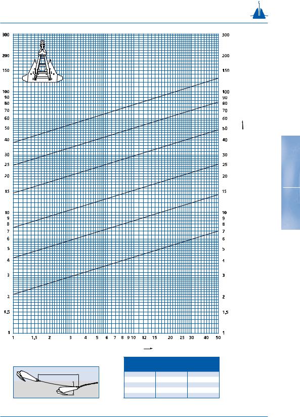
Stevpris Mk5 size in t |
|
|
|
|
|
|
|
|
|
|
|
|
|
|
|
|
|
|
|
||
|
|
anchor load |
|
|
|
|
drag |
|
|
|
|
penetration |
|
|||||||||
|
|
as % of |
|
|
|
|
|
% max |
|
|
|
as % max |
|
|||||||||
drag |
|
UHC |
|
|
|
|
|
|
|
drag |
|
|
|
|
penetration |
|
||||||
|
|
70 |
|
|
|
|
|
|
|
|
|
48 |
|
|
|
|
|
|
80 |
|
||
|
|
|
|
|
|
|
|
|
|
|
|
|
|
|
|
|
|
|
||||
|
|
|
60 |
|
|
|
|
|
|
|
|
|
37 |
|
|
|
|
|
|
68 |
|
|
|
|
|
50 |
|
|
|
|
|
|
|
|
|
27 |
|
|
|
|
|
|
55 |
|
|
|
netration |
|
40 |
|
|
|
|
|
|
|
|
|
18 |
|
|
|
|
|
|
42 |
|
|
|
|
30 |
|
|
|
|
|
|
|
|
|
9 |
|
|
|
|
|
|
23 |
|
||
|
|
|
|
|
|
|
|
|
|
|
|
|
|
|
|
|
|
|
||||
Example: loading 70% of ultimate holding capacity corresponds with 48% of maximum drag and 80% of maximum penetration at ultimate holding capacity.


 MTC
MTC