

- •Introduction to the Anchor Handling Course
- •Technical Specifications:
- •Winch Layout:
- •Power Settings / Bollard Pull
- •All operations on board must be performed in accordance with Company Procedures.
- •Risk Assessment
- •Planning
- •Planning:
- •Goal, example:
- •What to do:
- •Electrical winches
- •Winch operation
- •General Arrangement
- •A/H-Drum at full Capacity
- •Over speed
- •Water brake
- •Band brake
- •QUICK & Full Release
- •Hydraulic Winches
- •Lay out (B-type)
- •Hydraulic winch, “B-type”
- •TOWCON
- •Instruction for use of Wire Drums
- •Changing of Chain Wheels (Wildcats / Chain Lifter)
- •TRIPLEX - SHARK JAW SYSTEM.
- •Operation
- •Maintenance and inspections
- •Safety
- •2. OPERATION:
- •QUICK RELEASE:
- •EMERGENCY RELEASE:
- •CONTROL PANEL
- •Marks for Locked on Hinge Link
- •2.2- OPERATION OF THE "JAW IN POSITION ACCEPT" LEVER:
- •2.3 OPERATION OF THE CONTROL PANEL AT EMERGENCY POWER.
- •3. ELECTRIC AND HYDRAULIC POWER SYSTEM.
- •3. 1. ARRANGEMENT OF SYSTEM.
- •3.2. FUNCTIONING OF QUICK RELEASE - JAWS ONLY.
- •3.3. FUNCTIONING OF EMERGENCY RELEASE
- •4.2 Test without Load.
- •4.3 Test with Load.
- •5. General Maintenance
- •5.1 Accumulators Depressurising
- •5.2 Shark Jaw Unit
- •5.3 Guide Pins Units
- •5.4 Hydraulic System
- •5.5 Electric System
- •6. Control Measurements / Adjustments.
- •6.2 Adjustment of inductive proximity switches on lock cylinders.
- •6.3 Adjustment of Pressure Switches for Lock Pressure.
- •7. Test Program – Periodical Control
- •7.2 Checking List – Periodic Control Mechanical / Hydraulic.
- •7.3 Checking List – Periodic Control Electrical
- •7.4 Testing without Load – Yearly Testing.
- •7.5 Load Test – Emergency Release – 5 Year Control.
- •“Mark on line !”
- •“Double set of Jaws, Pins and Wire lifter”
- •View from the bridge.
- •“JAW READY FOR OPERATION”
- •“JAW LOCK POSITION ACCEPTED”
- •KARM FORK – SHARK JAW SYSTEM.
- •Wire and chain Stopper
- •Inserts for KARM FORK
- •Martensite:
- •Recommendations:
- •1. THE BASIC ELEMENTS OF STEEL WIRE ROPE
- •2. STEEL WIRE ROPE CONSTRUCTIONS
- •3. SPECIAL STEEL WIRE ROPES
- •4. USE OF STEEL WIRE ROPE
- •5. SELECTING THE RIGHT STEEL WIRE ROPE
- •6. ORDERING STEEL WIRE ROPE
- •7. STEEL WIRE ROPE TOLERANCES
- •8. HANDLING, INSPECTION AND INSTALLATION
- •9. INSPECTION AND MAINTENANCE
- •10. ELONGATION AND PRE-STRETCHING
- •11. OPERATING TEMPERATURES
- •12. MARTENSITE FORMATION
- •13. END TERMINATIONS
- •14. SOCKETING (WIRELOCK)
- •15. DRUM CAPACITY
- •16. CLASSIFICATION AND USE OF STEEL WIRE ROPE
- •17. ROPES
- •18. CHAINS AND LIFTING COMPONENTS
- •19. TECHNICAL CONVERSION TABLES
- •SWIVEL
- •MoorLink Swivel
- •Pin Extractor
- •Socket Bench
- •Chains and Fittings
- •STUD LINK MOORING CHAIN
- •OPEN LINK MOORING CHAIN
- •KENTER JOINING LINKS
- •PEAR SHAPE ANCHOR CONNECTING LINK
- •DETACHABLE CONNECTING LINK
- •D’ TYPE JOINING SHACKLES
- •‘D’ TYPE ANCHOR SHACKLES
- •SHACKLES
- •JAW & JAW SWIVELS
- •BOW & EYE SWIVELS
- •MOORING RINGS
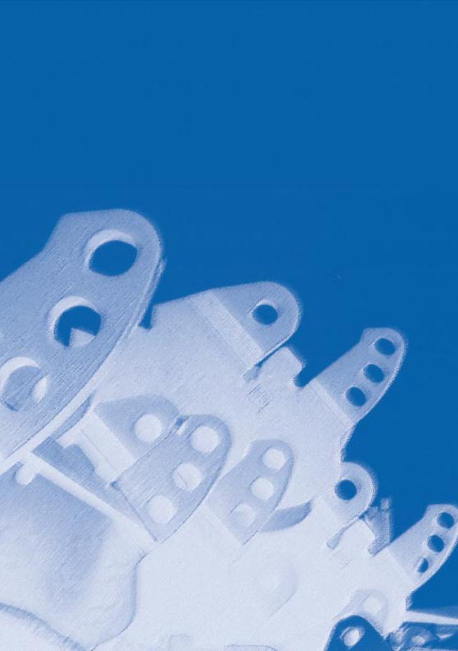
- •FISH PLATES
- •PELICAN HOOKS
- •SLIP HOOKS
- •‘J’ CHASERS
- •PERMANENT CHASERS
- •DETACHABLE PERMANENT CHAIN CHASERS
- •PERMANENT WIRE CHASERS
- •‘J’ LOCK CHAIN CHASERS
- •The way to break the anchor loose of the bottom is therefore:
- •Table of contents
- •Introduction
- •General
- •Mooring systems
- •Mooring components
- •History of drag embedment anchors
- •Characteristics of anchor types
- •History of vryhof anchor designs
- •Criteria for anchor holding capacity
- •Theory
- •Criteria for good anchor design
- •Aspects of soil mechanics in anchor design
- •Soil classification
- •Fluke/shank angle
- •Fluke area
- •Strength of an anchor design
- •Anchor loads and safety factors
- •Anchor behaviour in the soil
- •Proof loads for high holding power anchors
- •Anchor tests
- •Soil table
- •Practice
- •Introduction
- •Soil survey
- •Pile or anchor
- •Setting the fluke/shank angle
- •Connecting a swivel to the Stevpris anchor
- •Chasers
- •Chaser types
- •Stevpris installation
- •Laying anchors
- •Retrieving anchors
- •Anchor orientation
- •Decking the Stevpris anchor
- •What not to do!
- •Racking the Stevpris
- •Deploying Stevpris from the anchor rack
- •Boarding the anchor in deep water
- •Ballast In fluke
- •Chaser equilibrium
- •Deployment for permanent moorings
- •Piggy-backing
- •Piggy-back methods
- •Stevmanta VLA installation
- •Installation procedure
- •Stevmanta retrieval
- •Double line installation procedure
- •Stevmanta retrieval
- •Double line installation with Stevtensioner
- •The Stevtensioner
- •The working principle of the tensioner
- •Measurement of the tensions applied
- •Umbilical cable and measuring pin
- •Break - link
- •Duration of pretensioning anchors and piles
- •Handling the Stevtensioner
- •General tensioning procedures
- •Hook-up
- •Lowering
- •Tensioning mode
- •Retrieving
- •Supply vessels/anchor handling vessels
- •Product data
- •Introduction
- •Dimensions of vryhof anchor types
- •Proof load test for HHP anchors (US units)
- •Dimensions of vryhof tensioners
- •Proof load/break load of chains (in US units)
- •Chain components and forerunners
- •Connecting links
- •Conversion table
- •Mooring line catenary
- •Mooring line holding capacity
- •Shackles
- •Wire Rope
- •Wire rope sockets
- •Thimbles
- •Synthetic ropes
- •Mooring hawsers
- •Main dimensions chasers
- •Stevin Mk3 UHC chart
- •Stevin Mk3 drag and penetration chart
- •Stevpris Mk5 UHC chart
- •Stevpris Mk5 drag and penetration chart
- •Stevmanta VLA UPC chart
- •Introduction
- •Propulsion system
- •Propellers
- •Thrusters
- •Rudders
- •Manoeuvring
- •Current
- •Wind
- •Other forces
- •Turning point (Pivot point)
- •Ship handling
- •General layout Jack-Up drilling unit:
- •General information about a Semi Submersible drilling unit:

1
General

Mooring systems
Mooring systems have been around just as long as man has felt the need for anchoring a vessel at sea. These systems were used, and are still used, on ships and consisted of one or more lines connected to the bow or stern of the ship. Generally the ships stayed moored for a short duration of time (days).
When the exploration and production of oil and gas started offshore, a need for more permanent mooring systems became apparent. Numerous different mooring systems have been developed over the years, of which a short selection is presented here.
Semi-submersible drilling rig - generally the semisubmersibles are moored using an eight point mooring. Two mooring lines come together at each of the columns of the semi-submersible.
CALM buoy - generally the buoy will be moored using four or more mooring lines at equally spaced angles. The mooring lines generally have a catenary shape. The vessel connects to the buoy with a single line and is free to weathervane around the buoy.
SALM buoy - these types of buoys have a mooring that consists of a single mooring line attached to an anchor point on the seabed, underneath the buoy. The anchor point may be gravity based or piled.
Turret mooring - this type of mooring is generally used on FPSOs and FSOs in more harsh environments. Multiple mooring lines are used, which come together at the turntable built into the FPSO or FSO. The FPSO or FSO is able to rotate around the turret to obtain an optimal orientation relative to the prevailing weather conditions.
Spread mooring - generally used on FPSOs and FSOs in milder environments. The mooring lines are directly connected to the FPSO or FSO at both the stern and bow of the vessel.
semi-sub mooring |
9
typical turret mooring
Mooring systems
When oil and gas exploration and production was conducted in shallow to deep water, the most common mooring line configuration was the catenary mooring line consisting of chain or wire rope. For exploration and production in deep to ultra-deep water, the weight of the mooring line starts to become a limiting factor in the design of the floater. To overcome this problem new solutions were developed consisting of synthetic ropes in the mooring line (less weight) and/or a taut leg mooring system
(fig. 1-01 and fig. 1-02).
The major difference between a catenary mooring and a taut leg mooring is that where the catenary mooring arrives at the seabed horizontally, the taut leg mooring arrives at the seabed at an angle. This
10means that in a taut leg mooring the anchor point has to be capable of resisting both horizontal and vertical
forces, while in a catenary mooring the anchor point is only subjected to horizontal forces. In a catenary mooring, most of the restoring forces are generated by the weight of the mooring line. In a taut leg mooring, the restoring forces are generated by the elasticity of the mooring line.
An advantage of a taut leg mooring over the catenary mooring is that the footprint of the taut leg mooring is smaller than the footprint of the catenary mooring, i.e. the mooring radius of the taut leg mooring will be smaller than the mooring radius of a catenary mooring for a similar application.
catenary system
fig. 1-01
taut leg system
fig. 1-02