

- •Introduction to the Anchor Handling Course
- •Technical Specifications:
- •Winch Layout:
- •Power Settings / Bollard Pull
- •All operations on board must be performed in accordance with Company Procedures.
- •Risk Assessment
- •Planning
- •Planning:
- •Goal, example:
- •What to do:
- •Electrical winches
- •Winch operation
- •General Arrangement
- •A/H-Drum at full Capacity
- •Over speed
- •Water brake
- •Band brake
- •QUICK & Full Release
- •Hydraulic Winches
- •Lay out (B-type)
- •Hydraulic winch, “B-type”
- •TOWCON
- •Instruction for use of Wire Drums
- •Changing of Chain Wheels (Wildcats / Chain Lifter)
- •TRIPLEX - SHARK JAW SYSTEM.
- •Operation
- •Maintenance and inspections
- •Safety
- •2. OPERATION:
- •QUICK RELEASE:
- •EMERGENCY RELEASE:
- •CONTROL PANEL
- •Marks for Locked on Hinge Link
- •2.2- OPERATION OF THE "JAW IN POSITION ACCEPT" LEVER:
- •2.3 OPERATION OF THE CONTROL PANEL AT EMERGENCY POWER.
- •3. ELECTRIC AND HYDRAULIC POWER SYSTEM.
- •3. 1. ARRANGEMENT OF SYSTEM.
- •3.2. FUNCTIONING OF QUICK RELEASE - JAWS ONLY.
- •3.3. FUNCTIONING OF EMERGENCY RELEASE
- •4.2 Test without Load.
- •4.3 Test with Load.
- •5. General Maintenance
- •5.1 Accumulators Depressurising
- •5.2 Shark Jaw Unit
- •5.3 Guide Pins Units
- •5.4 Hydraulic System
- •5.5 Electric System
- •6. Control Measurements / Adjustments.
- •6.2 Adjustment of inductive proximity switches on lock cylinders.
- •6.3 Adjustment of Pressure Switches for Lock Pressure.
- •7. Test Program – Periodical Control
- •7.2 Checking List – Periodic Control Mechanical / Hydraulic.
- •7.3 Checking List – Periodic Control Electrical
- •7.4 Testing without Load – Yearly Testing.
- •7.5 Load Test – Emergency Release – 5 Year Control.
- •“Mark on line !”
- •“Double set of Jaws, Pins and Wire lifter”
- •View from the bridge.
- •“JAW READY FOR OPERATION”
- •“JAW LOCK POSITION ACCEPTED”
- •KARM FORK – SHARK JAW SYSTEM.
- •Wire and chain Stopper
- •Inserts for KARM FORK
- •Martensite:
- •Recommendations:
- •1. THE BASIC ELEMENTS OF STEEL WIRE ROPE
- •2. STEEL WIRE ROPE CONSTRUCTIONS
- •3. SPECIAL STEEL WIRE ROPES
- •4. USE OF STEEL WIRE ROPE
- •5. SELECTING THE RIGHT STEEL WIRE ROPE
- •6. ORDERING STEEL WIRE ROPE
- •7. STEEL WIRE ROPE TOLERANCES
- •8. HANDLING, INSPECTION AND INSTALLATION
- •9. INSPECTION AND MAINTENANCE
- •10. ELONGATION AND PRE-STRETCHING
- •11. OPERATING TEMPERATURES
- •12. MARTENSITE FORMATION
- •13. END TERMINATIONS
- •14. SOCKETING (WIRELOCK)
- •15. DRUM CAPACITY
- •16. CLASSIFICATION AND USE OF STEEL WIRE ROPE
- •17. ROPES
- •18. CHAINS AND LIFTING COMPONENTS
- •19. TECHNICAL CONVERSION TABLES
- •SWIVEL
- •MoorLink Swivel
- •Pin Extractor
- •Socket Bench
- •Chains and Fittings
- •STUD LINK MOORING CHAIN
- •OPEN LINK MOORING CHAIN
- •KENTER JOINING LINKS
- •PEAR SHAPE ANCHOR CONNECTING LINK
- •DETACHABLE CONNECTING LINK
- •D’ TYPE JOINING SHACKLES
- •‘D’ TYPE ANCHOR SHACKLES
- •SHACKLES
- •JAW & JAW SWIVELS
- •BOW & EYE SWIVELS
- •MOORING RINGS
- •FISH PLATES
- •PELICAN HOOKS
- •SLIP HOOKS
- •‘J’ CHASERS
- •PERMANENT CHASERS
- •DETACHABLE PERMANENT CHAIN CHASERS
- •PERMANENT WIRE CHASERS
- •‘J’ LOCK CHAIN CHASERS
- •The way to break the anchor loose of the bottom is therefore:
- •Table of contents
- •Introduction
- •General
- •Mooring systems
- •Mooring components
- •History of drag embedment anchors
- •Characteristics of anchor types
- •History of vryhof anchor designs
- •Criteria for anchor holding capacity
- •Theory
- •Criteria for good anchor design
- •Aspects of soil mechanics in anchor design
- •Soil classification
- •Fluke/shank angle
- •Fluke area
- •Strength of an anchor design
- •Anchor loads and safety factors
- •Anchor behaviour in the soil
- •Proof loads for high holding power anchors
- •Anchor tests
- •Soil table
- •Practice
- •Introduction
- •Soil survey
- •Pile or anchor
- •Setting the fluke/shank angle
- •Connecting a swivel to the Stevpris anchor
- •Chasers
- •Chaser types
- •Stevpris installation
- •Laying anchors
- •Retrieving anchors
- •Anchor orientation
- •Decking the Stevpris anchor
- •What not to do!
- •Racking the Stevpris
- •Deploying Stevpris from the anchor rack
- •Boarding the anchor in deep water
- •Ballast In fluke
- •Chaser equilibrium
- •Deployment for permanent moorings
- •Piggy-backing
- •Piggy-back methods
- •Stevmanta VLA installation
- •Installation procedure
- •Stevmanta retrieval
- •Double line installation procedure
- •Stevmanta retrieval
- •Double line installation with Stevtensioner
- •The Stevtensioner
- •The working principle of the tensioner
- •Measurement of the tensions applied
- •Umbilical cable and measuring pin
- •Break - link
- •Duration of pretensioning anchors and piles
- •Handling the Stevtensioner
- •General tensioning procedures
- •Hook-up
- •Lowering
- •Tensioning mode
- •Retrieving
- •Supply vessels/anchor handling vessels
- •Product data
- •Introduction
- •Dimensions of vryhof anchor types
- •Proof load test for HHP anchors (US units)
- •Dimensions of vryhof tensioners
- •Proof load/break load of chains (in US units)
- •Chain components and forerunners
- •Connecting links
- •Conversion table
- •Mooring line catenary
- •Mooring line holding capacity
- •Shackles
- •Wire Rope
- •Wire rope sockets
- •Thimbles
- •Synthetic ropes
- •Mooring hawsers
- •Main dimensions chasers
- •Stevin Mk3 UHC chart
- •Stevin Mk3 drag and penetration chart
- •Stevpris Mk5 UHC chart
- •Stevpris Mk5 drag and penetration chart
- •Stevmanta VLA UPC chart
- •Introduction
- •Propulsion system
- •Propellers
- •Thrusters
- •Rudders
- •Manoeuvring
- •Current
- •Wind
- •Other forces
- •Turning point (Pivot point)
- •Ship handling
- •General layout Jack-Up drilling unit:
- •General information about a Semi Submersible drilling unit:
Mooring components
A typical mooring system can be divided in three different components, the mooring line, the connectors and the anchor point.
Mooring line
Chain
The most common product used for mooring lines is chain which is available in different diameters and grades. Two different designs of chain are used frequently, studlink and studless chain. The studlink chain is most commonly used for moorings that have to be reset numerous times during their lifetime, for instance semi-submersibles, while studless link chain is often used for permanent moorings (FPSOs, buoys, FSOs). A chain mooring line can be terminated in either a common link or an end link (fig. 1-03).
Wire rope
When compared to chain, wire rope has a lower weight than chain, for the same breaking load and a higher elasticity. Common wire ropes used in offshore mooring lines are six strand and spiral strand. The wire rope is terminated with a socket (for instance open spelter, closed spelter, CR) for connection to the other components in the mooring system. Generally wire rope is more prone to damage and corrosion than chain (fig. 1-04).
Synthetic fibre rope
A recent development is the use of synthetic fibre ropes as mooring line. Typical materials that can be used are polyester and high modulus polyethylene (Dyneema). The major advantage of synthetic fibre ropes is the light weight of the material and the high elasticity. The synthetic fibre rope is generally terminated with a special spool and shackle for connection to the other components in the mooring system.
fig. 1-03
fig. 1-04
11

Mooring components
Connectors
Shackles
The shackle is a connector that is very common in the offshore industry. It consists of a bow, which is closed by a pin. Many different types of shackles are available, depending on the application. The shackle can be used in both temporary and permanent moorings
(fig. 1-05).
Connecting link kenter type
The connecting link kenter type is most commonly used for the connection of two pieces of chain mooring line, where the terminations of the two pieces have the same dimensions. The connecting link kenter type has the same outside length as a chain
12link of the same diameter. Generally connecting links kenter type are not used in permanent mooring
systems, as they have a shorter fatigue life than the chain (fig. 1-06).
Connecting link pear shaped
The pear shaped connecting link is similar to the connecting link kenter type, except that it is used for the connection of two pieces of mooring line with terminations that have different dimensions. Like the connecting link kenter type, the pear shaped connecting links are not used in permanent mooring systems
(fig. 1-07).
Connecting link c type
Like the connecting link kenter type, the connecting link c type is used for the connection of two pieces of mooring line with terminations that have the same dimensions. The major difference between the kenter type and the c type is the way that the connector is opened and closed. This connector is generally not used in permanent moorings (fig. 1-08).
fig. 1-05
fig. 1-06
fig. 1-07
fig. 1-08

Mooring components
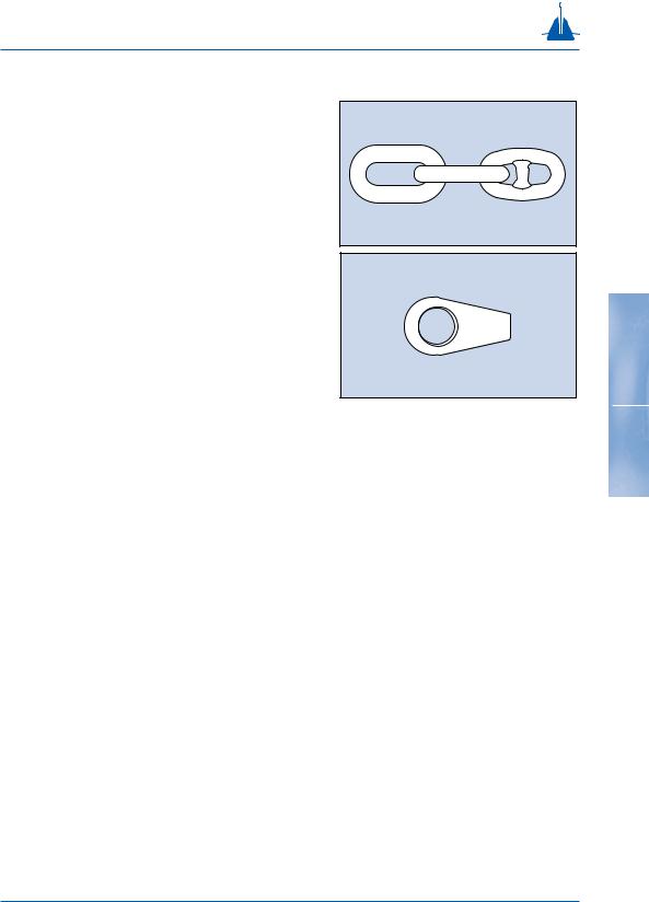
Swivels
A swivel is used in a mooring system, generally of a temporary type, to relieve the twist and torque that builds up in the mooring line. The swivel is often placed a few links from the anchor point, although it can also be placed between a section of chain and a section of wire rope. There are many different types of swivels available, although a disadvantage of most common swivels is that they may not function while under load, which is caused by high friction inside the turning mechanism. A new development is swivels that are capable of swivelling under load, due to special bearing surfaces inside the mechanism (fig. 1-09).
Anchoring point
Dead weight
The dead weight is probably the oldest anchor in existence. The holding capacity is generated by the weight of the material used and partly by the friction between the dead weight and the seabed. Common materials in use today for dead weights are steel and concrete (fig. 1-10).
Drag embedment anchor
This is the most popular type of anchoring point available today. The drag embedment anchor has been designed to penetrate into the seabed, either partly of fully. The holding capacity of the drag embedment anchor is generated by the resistance of the soil in front of the anchor. The drag embedment anchor is very well suited for resisting large horizontal loads, but not for large vertical loads although there are some drag embedment anchors available on the market today that can resist significant vertical loads
(fig. 1-11).
fig. 1-09
13
fig. 1-10
fig. 1-11

Mooring components
Pile
The pile is a hollow steel pipe that is installed into the seabed by means of a piling hammer or vibrator. The holding capacity of the pile is generated by the friction of the soil along the pile and lateral soil resistance. Generally the pile has to be installed at great depth below seabed to obtain the required holding capacity. The pile is capable of resisting both horizontal and vertical loads (fig. 1-12).
Suction anchor
Like the pile, the suction anchor is a hollow steel pipe, although the diameter of the pipe is much larger than that of the pile. The suction anchor is forced into the seabed by means of a pump connected to the top of the pipe, creating a pressure difference. When
14pressure inside the pipe is lower than outside, the pipe is sucked into the seabed. After installation the
pump is removed. The holding capacity of the suction anchor is generated by the friction of the soil along the suction anchor and lateral soil resistance. The suction anchor is capable of withstanding both horizontal and vertical loads (fig. 1-13).
Vertical load anchor
A new development is the vertical load anchor (VLA). The vertical load anchor is installed like a conventional drag embedment anchor, but penetrates much deeper. When the anchor mode is changed from the installation mode to the vertical (normal) loading mode, the anchor can withstand both horizontal and vertical loads (fig. 1-14).
fig. 1-12
fig. 1-13
fig. 1-14