- •Introduction to the Anchor Handling Course
- •Technical Specifications:
- •Winch Layout:
- •Power Settings / Bollard Pull
- •All operations on board must be performed in accordance with Company Procedures.
- •Risk Assessment
- •Planning
- •Planning:
- •Goal, example:
- •What to do:
- •Electrical winches
- •Winch operation
- •General Arrangement
- •A/H-Drum at full Capacity
- •Over speed
- •Water brake
- •Band brake
- •QUICK & Full Release
- •Hydraulic Winches
- •Lay out (B-type)
- •Hydraulic winch, “B-type”
- •TOWCON
- •Instruction for use of Wire Drums
- •Changing of Chain Wheels (Wildcats / Chain Lifter)
- •TRIPLEX - SHARK JAW SYSTEM.
- •Operation
- •Maintenance and inspections
- •Safety
- •2. OPERATION:
- •QUICK RELEASE:
- •EMERGENCY RELEASE:
- •CONTROL PANEL
- •Marks for Locked on Hinge Link
- •2.2- OPERATION OF THE "JAW IN POSITION ACCEPT" LEVER:
- •2.3 OPERATION OF THE CONTROL PANEL AT EMERGENCY POWER.
- •3. ELECTRIC AND HYDRAULIC POWER SYSTEM.
- •3. 1. ARRANGEMENT OF SYSTEM.
- •3.2. FUNCTIONING OF QUICK RELEASE - JAWS ONLY.
- •3.3. FUNCTIONING OF EMERGENCY RELEASE
- •4.2 Test without Load.
- •4.3 Test with Load.
- •5. General Maintenance
- •5.1 Accumulators Depressurising
- •5.2 Shark Jaw Unit
- •5.3 Guide Pins Units
- •5.4 Hydraulic System
- •5.5 Electric System
- •6. Control Measurements / Adjustments.
- •6.2 Adjustment of inductive proximity switches on lock cylinders.
- •6.3 Adjustment of Pressure Switches for Lock Pressure.
- •7. Test Program – Periodical Control
- •7.2 Checking List – Periodic Control Mechanical / Hydraulic.
- •7.3 Checking List – Periodic Control Electrical
- •7.4 Testing without Load – Yearly Testing.
- •7.5 Load Test – Emergency Release – 5 Year Control.
- •“Mark on line !”
- •“Double set of Jaws, Pins and Wire lifter”
- •View from the bridge.
- •“JAW READY FOR OPERATION”
- •“JAW LOCK POSITION ACCEPTED”
- •KARM FORK – SHARK JAW SYSTEM.
- •Wire and chain Stopper
- •Inserts for KARM FORK
- •Martensite:
- •Recommendations:
- •1. THE BASIC ELEMENTS OF STEEL WIRE ROPE
- •2. STEEL WIRE ROPE CONSTRUCTIONS
- •3. SPECIAL STEEL WIRE ROPES
- •4. USE OF STEEL WIRE ROPE
- •5. SELECTING THE RIGHT STEEL WIRE ROPE
- •6. ORDERING STEEL WIRE ROPE
- •7. STEEL WIRE ROPE TOLERANCES
- •8. HANDLING, INSPECTION AND INSTALLATION
- •9. INSPECTION AND MAINTENANCE
- •10. ELONGATION AND PRE-STRETCHING
- •11. OPERATING TEMPERATURES
- •12. MARTENSITE FORMATION
- •13. END TERMINATIONS
- •14. SOCKETING (WIRELOCK)
- •15. DRUM CAPACITY
- •16. CLASSIFICATION AND USE OF STEEL WIRE ROPE
- •17. ROPES
- •18. CHAINS AND LIFTING COMPONENTS
- •19. TECHNICAL CONVERSION TABLES
- •SWIVEL
- •MoorLink Swivel
- •Pin Extractor
- •Socket Bench
- •Chains and Fittings
- •STUD LINK MOORING CHAIN
- •OPEN LINK MOORING CHAIN
- •KENTER JOINING LINKS
- •PEAR SHAPE ANCHOR CONNECTING LINK
- •DETACHABLE CONNECTING LINK
- •D’ TYPE JOINING SHACKLES
- •‘D’ TYPE ANCHOR SHACKLES
- •SHACKLES
- •JAW & JAW SWIVELS
- •BOW & EYE SWIVELS
- •MOORING RINGS
- •FISH PLATES
- •PELICAN HOOKS
- •SLIP HOOKS
- •‘J’ CHASERS
- •PERMANENT CHASERS
- •DETACHABLE PERMANENT CHAIN CHASERS
- •PERMANENT WIRE CHASERS
- •‘J’ LOCK CHAIN CHASERS
- •The way to break the anchor loose of the bottom is therefore:
- •Table of contents
- •Introduction
- •General
- •Mooring systems
- •Mooring components
- •History of drag embedment anchors
- •Characteristics of anchor types
- •History of vryhof anchor designs
- •Criteria for anchor holding capacity
- •Theory
- •Criteria for good anchor design
- •Aspects of soil mechanics in anchor design
- •Soil classification
- •Fluke/shank angle
- •Fluke area
- •Strength of an anchor design
- •Anchor loads and safety factors
- •Anchor behaviour in the soil
- •Proof loads for high holding power anchors
- •Anchor tests
- •Soil table
- •Practice
- •Introduction
- •Soil survey
- •Pile or anchor
- •Setting the fluke/shank angle
- •Connecting a swivel to the Stevpris anchor
- •Chasers
- •Chaser types
- •Stevpris installation
- •Laying anchors
- •Retrieving anchors
- •Anchor orientation
- •Decking the Stevpris anchor
- •What not to do!
- •Racking the Stevpris
- •Deploying Stevpris from the anchor rack
- •Boarding the anchor in deep water
- •Ballast In fluke
- •Chaser equilibrium
- •Deployment for permanent moorings
- •Piggy-backing
- •Piggy-back methods
- •Stevmanta VLA installation
- •Installation procedure
- •Stevmanta retrieval
- •Double line installation procedure
- •Stevmanta retrieval
- •Double line installation with Stevtensioner
- •The Stevtensioner
- •The working principle of the tensioner
- •Measurement of the tensions applied
- •Umbilical cable and measuring pin
- •Break - link
- •Duration of pretensioning anchors and piles
- •Handling the Stevtensioner
- •General tensioning procedures
- •Hook-up
- •Lowering
- •Tensioning mode
- •Retrieving
- •Supply vessels/anchor handling vessels
- •Product data
- •Introduction
- •Dimensions of vryhof anchor types
- •Proof load test for HHP anchors (US units)
- •Dimensions of vryhof tensioners
- •Proof load/break load of chains (in US units)
- •Chain components and forerunners
- •Connecting links
- •Conversion table
- •Mooring line catenary
- •Mooring line holding capacity
- •Shackles
- •Wire Rope
- •Wire rope sockets
- •Thimbles
- •Synthetic ropes
- •Mooring hawsers
- •Main dimensions chasers
- •Stevin Mk3 UHC chart
- •Stevin Mk3 drag and penetration chart
- •Stevpris Mk5 UHC chart
- •Stevpris Mk5 drag and penetration chart
- •Stevmanta VLA UPC chart
- •Introduction
- •Propulsion system
- •Propellers
- •Thrusters
- •Rudders
- •Manoeuvring
- •Current
- •Wind
- •Other forces
- •Turning point (Pivot point)
- •Ship handling
- •General layout Jack-Up drilling unit:
- •General information about a Semi Submersible drilling unit:
History of drag embedment anchors
History traces the use of anchors to China as far back as 2,000 BC, though it is quite probable that they were used prior to this. At that time the general tendency was to use large stones, baskets of stones, bags of sand or even logs of wood loaded with lead which were then fastened to lines. It was this weight as well as a certain degree of friction on the bottom which secured a vessel in position.
With the introduction of iron into anchor construction, teeth or flukes were built on the anchor, allowing penetration into the seabed, thus offering additional stability. Yet these primitive anchors were of poor construction and often broke under pressure. Curved arms were introduced in 1813, and from 1852, the so-called ‘Admiralty Anchor’ was used for ships of
the Royal Navy. Another refinement in the 19th 15 century was the elimination of the stock, the crosspiece
at the top of an anchor which ensured that the positioning of the anchor would allow the flukes to penetrate the soil. A stockless anchor was invented in 1821 and became popular, primarily as a result of the ease of handling and stowing, qualities still valued today.
A large number of anchor types has been designed and commercialised over the years. Some have prospered, others not. The most recent designs are the results of vast experience and extensive testing, and are far more efficient than their historical predecessors. A short overview of the anchors in use today, is presented on the following pages.
Characteristics of anchor types
|
Based upon certain charateristics such as fluke |
|
|
|
area, shank, stabilisers, it is possible to classify |
|
|
|
the various anchor types. |
|
|
|
To allow a rough comparison of anchor type |
|
|
|
efficiency, an indication (*) is provided for a 10 t |
Class A |
Stevpris |
|
anchor as (HOLDING CAPACITY = WEIGHT * EFFICIENCY). |
|
|
|
Class A efficiency range *33 to 55 |
|
|
|
slender anchors with ultra-penetration. |
|
|
|
|
Class B |
Bruce SS |
|
Class B efficiency range *17 to 25 |
|
|
|
anchors with ‘elbowed’ shank, allowing for |
|
|
|
improved penetration. |
|
|
|
Class C efficiency range *14 to 26 |
|
|
16 |
anchors with open crown hinge near the |
Class C |
Stevin |
|
centre of gravity and relatively short shank |
|
|
|
and stabilisers or built-in stabilisers. |
|
|
|
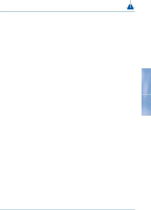
Class D efficiency range *8 to 15 |
|
|
|
anchors with hinge and stabilisers at the rear |
|
|
|
and relatively long shanks and stabilisers. |
Class D |
Danforth |
|
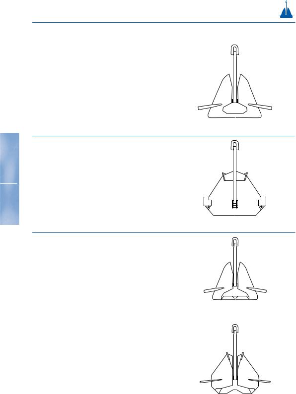
Class E efficiency range *8 to 11 |
|
|
|
anchors with very short, thick stabilisers; hinge |
|
|
|
at the rear and a relatively short, more or less |
|
|
|
square-shaped shank. |
|
|
|
|
Class E |
AC14 |
|
Class F efficiency range *4 to 6 |
|
|
|
anchors with square shank, no stock stabilisers. |
|
|
|
The stabilising resistance is built-in the crown. |
|
|
|
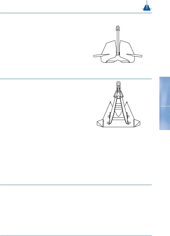
Class G efficiency range *<6 |
|
|
|
anchors with small fluke area and stabilisers at |
Class F |
US Navy Stockless |
|
the front of the shank. |
|
|
Class G Single Fluke Stock
Characteristics of anchor types
Stevshark |
FFTS |
Bruce TS |
Hook |
Stevfix |
Stevmud |
Flipper Delta |
17 |
LWT |
Moorfast - Stato - Offdrill |
Boss |
Stokes |
Snugstow |
Weldhold |
Beyers |
Union |
Spek |
Stock |
Dredger |
Mooring Anchor |
|
|
|
History of vryhof anchor designs
A brief chronological summary of the types of |
Stevin |
anchors vryhof has designed for use in the offshore |
|
and dredging industries: |
|
• 1972 - The Stevin anchor: The original design. The wing was not yet enlarged. The anchor had a square shank. It is no longer manufactured.
• 1974 - The Hook anchor: originally designed for |
Hook |
permanent moorings. This design was sur- |
|
passed in 1980 by the Stevpris design and is |
|
no longer manufactured. |
|
18
• 1977 - The Stevin Mk3 anchor: is the improved |
|
Stevin Mk3 |
|
|||||
|
version of the original Stevin anchor. It was |
|
|
|
||||
|
equipped with an enlarged crown and fluke |
|
|
|
||||
|
area and a streamlined shank for more effi- |
|
|
|
||||
|
cient penetration. This anchor is still manu- |
|
|
|
||||
|
factured and in use in offshore and dredging |
|
|
|
|
|
|
|
|
activities. It has all classification societies |
|
|
|
||||
|
approvals. |
|
|
|
||||
|
|
|
|
|
||||
• 1978 - The Stevfix anchor: this anchor was |
|
Stevfix |
|
|||||
|
designed with special fluke points for harder |
|
|
|
||||
|
soils and a larger fluke area than the Stevin, |
|
|
|
||||
|
but has been surpassed by the Stevpris |
|
|
|
||||
|
anchor. It is no longer manufactured. |
|
|
|
||||
|
|
|
|
|
|
|
|
|
History of vryhof anchor designs
• 1979 - The Stevmud anchor: the Stevmud is essen- |
|
Stevmud |
tially the Stevin anchor with a considerably |
|
|
enlarged fluke area. This anchor type was |
|
|
also surpassed by the Stevpris anchor and is |
|
|
no longer manufactured. |
|
|
|
|
|
|
|
|
|
|
|
• 1980 - The introduction of the Stevpris and Stevshark anchors. The Stevpris anchor is a deep penetrating anchor with a plough shaped shank, surpassing the performance of all earlier designs in the vryhof range, and incorporating the latest experience, research and knowledge of the anchor designer. The Stevshark anchor is a specially reinforced Stevpris anchor, equipped with a serrated shank and cutter-teeth for better penetration in hard soils, such as coral types or sandstone. The fluke points are specially reinforced to withstand high point loads.
Stevpris
19
History of vryhof anchor designs
•1990 - The Stevpris Mk5 and Stevshark Mk5 |
Stevshark Mk5 |
were introduced. The improved versions of |
|
the original Stevpris and Stevshark anchors. |
|
Improvements have concentrated on two |
|
features: higher holding capacity and easier |
|
handling. |
|
|
•1996 - Introduction of the Stevmanta VLA |
Stevmanta |
|
(Vertical Load Anchor). Based on industry |
|
|
demand for an anchor that could withstand |
|
|
vertical loads, the Stevmanta VLA was deve- |
|
|
loped. The Stevmanta VLA is a new design in |
|
20 |
which a traditionally rigid shank has been |
|
|
replaced by a system of wires connected to a |
|
|
plate. The anchor is designed to accept verti- |
|
|
cal (or normal) loads and is installed as a |
|
|
conventional drag embedment anchor with a |
|
|
horizontal load to the mudline to obtain the |
|
|
deepest penetration possible. By changing |
|
|
the point of pulling at the anchor, vertical (or |
|
|
normal) loading of the fluke is obtained thus |
|
|
mobilising the maximum possible soil resi- |
|
|
stance. As a VLA is deeply embedded and |
|
|
always loaded in a direction normal to the |
|
|
fluke, the load can be applied in any |
|
|
direction. Consequently the anchor is ideal |
|
|
for taut-leg mooring systems. |
|