
- •Introduction to the Anchor Handling Course
- •Technical Specifications:
- •Winch Layout:
- •Power Settings / Bollard Pull
- •All operations on board must be performed in accordance with Company Procedures.
- •Risk Assessment
- •Planning
- •Planning:
- •Goal, example:
- •What to do:
- •Electrical winches
- •Winch operation
- •General Arrangement
- •A/H-Drum at full Capacity
- •Over speed
- •Water brake
- •Band brake
- •QUICK & Full Release
- •Hydraulic Winches
- •Lay out (B-type)
- •Hydraulic winch, “B-type”
- •TOWCON
- •Instruction for use of Wire Drums
- •Changing of Chain Wheels (Wildcats / Chain Lifter)
- •TRIPLEX - SHARK JAW SYSTEM.
- •Operation
- •Maintenance and inspections
- •Safety
- •2. OPERATION:
- •QUICK RELEASE:
- •EMERGENCY RELEASE:
- •CONTROL PANEL
- •Marks for Locked on Hinge Link
- •2.2- OPERATION OF THE "JAW IN POSITION ACCEPT" LEVER:
- •2.3 OPERATION OF THE CONTROL PANEL AT EMERGENCY POWER.
- •3. ELECTRIC AND HYDRAULIC POWER SYSTEM.
- •3. 1. ARRANGEMENT OF SYSTEM.
- •3.2. FUNCTIONING OF QUICK RELEASE - JAWS ONLY.
- •3.3. FUNCTIONING OF EMERGENCY RELEASE
- •4.2 Test without Load.
- •4.3 Test with Load.
- •5. General Maintenance
- •5.1 Accumulators Depressurising
- •5.2 Shark Jaw Unit
- •5.3 Guide Pins Units
- •5.4 Hydraulic System
- •5.5 Electric System
- •6. Control Measurements / Adjustments.
- •6.2 Adjustment of inductive proximity switches on lock cylinders.
- •6.3 Adjustment of Pressure Switches for Lock Pressure.
- •7. Test Program – Periodical Control
- •7.2 Checking List – Periodic Control Mechanical / Hydraulic.
- •7.3 Checking List – Periodic Control Electrical
- •7.4 Testing without Load – Yearly Testing.
- •7.5 Load Test – Emergency Release – 5 Year Control.
- •“Mark on line !”
- •“Double set of Jaws, Pins and Wire lifter”
- •View from the bridge.
- •“JAW READY FOR OPERATION”
- •“JAW LOCK POSITION ACCEPTED”
- •KARM FORK – SHARK JAW SYSTEM.
- •Wire and chain Stopper
- •Inserts for KARM FORK
- •Martensite:
- •Recommendations:
- •1. THE BASIC ELEMENTS OF STEEL WIRE ROPE
- •2. STEEL WIRE ROPE CONSTRUCTIONS
- •3. SPECIAL STEEL WIRE ROPES
- •4. USE OF STEEL WIRE ROPE
- •5. SELECTING THE RIGHT STEEL WIRE ROPE
- •6. ORDERING STEEL WIRE ROPE
- •7. STEEL WIRE ROPE TOLERANCES
- •8. HANDLING, INSPECTION AND INSTALLATION
- •9. INSPECTION AND MAINTENANCE
- •10. ELONGATION AND PRE-STRETCHING
- •11. OPERATING TEMPERATURES
- •12. MARTENSITE FORMATION
- •13. END TERMINATIONS
- •14. SOCKETING (WIRELOCK)
- •15. DRUM CAPACITY
- •16. CLASSIFICATION AND USE OF STEEL WIRE ROPE
- •17. ROPES
- •18. CHAINS AND LIFTING COMPONENTS
- •19. TECHNICAL CONVERSION TABLES
- •SWIVEL
- •MoorLink Swivel
- •Pin Extractor
- •Socket Bench
- •Chains and Fittings
- •STUD LINK MOORING CHAIN
- •OPEN LINK MOORING CHAIN
- •KENTER JOINING LINKS
- •PEAR SHAPE ANCHOR CONNECTING LINK
- •DETACHABLE CONNECTING LINK
- •D’ TYPE JOINING SHACKLES
- •‘D’ TYPE ANCHOR SHACKLES
- •SHACKLES
- •JAW & JAW SWIVELS
- •BOW & EYE SWIVELS
- •MOORING RINGS
- •FISH PLATES
- •PELICAN HOOKS
- •SLIP HOOKS
- •‘J’ CHASERS
- •PERMANENT CHASERS
- •DETACHABLE PERMANENT CHAIN CHASERS
- •PERMANENT WIRE CHASERS
- •‘J’ LOCK CHAIN CHASERS
- •The way to break the anchor loose of the bottom is therefore:
- •Table of contents
- •Introduction
- •General
- •Mooring systems
- •Mooring components
- •History of drag embedment anchors
- •Characteristics of anchor types
- •History of vryhof anchor designs
- •Criteria for anchor holding capacity
- •Theory
- •Criteria for good anchor design
- •Aspects of soil mechanics in anchor design
- •Soil classification
- •Fluke/shank angle
- •Fluke area
- •Strength of an anchor design
- •Anchor loads and safety factors
- •Anchor behaviour in the soil
- •Proof loads for high holding power anchors
- •Anchor tests
- •Soil table
- •Practice
- •Introduction
- •Soil survey
- •Pile or anchor
- •Setting the fluke/shank angle
- •Connecting a swivel to the Stevpris anchor
- •Chasers
- •Chaser types
- •Stevpris installation
- •Laying anchors
- •Retrieving anchors
- •Anchor orientation
- •Decking the Stevpris anchor
- •What not to do!
- •Racking the Stevpris
- •Deploying Stevpris from the anchor rack
- •Boarding the anchor in deep water
- •Ballast In fluke
- •Chaser equilibrium
- •Deployment for permanent moorings
- •Piggy-backing
- •Piggy-back methods
- •Stevmanta VLA installation
- •Installation procedure
- •Stevmanta retrieval
- •Double line installation procedure
- •Stevmanta retrieval
- •Double line installation with Stevtensioner
- •The Stevtensioner
- •The working principle of the tensioner
- •Measurement of the tensions applied
- •Umbilical cable and measuring pin
- •Break - link
- •Duration of pretensioning anchors and piles
- •Handling the Stevtensioner
- •General tensioning procedures
- •Hook-up
- •Lowering
- •Tensioning mode
- •Retrieving
- •Supply vessels/anchor handling vessels
- •Product data
- •Introduction
- •Dimensions of vryhof anchor types
- •Proof load test for HHP anchors (US units)
- •Dimensions of vryhof tensioners
- •Proof load/break load of chains (in US units)
- •Chain components and forerunners
- •Connecting links
- •Conversion table
- •Mooring line catenary
- •Mooring line holding capacity
- •Shackles
- •Wire Rope
- •Wire rope sockets
- •Thimbles
- •Synthetic ropes
- •Mooring hawsers
- •Main dimensions chasers
- •Stevin Mk3 UHC chart
- •Stevin Mk3 drag and penetration chart
- •Stevpris Mk5 UHC chart
- •Stevpris Mk5 drag and penetration chart
- •Stevmanta VLA UPC chart
- •Introduction
- •Propulsion system
- •Propellers
- •Thrusters
- •Rudders
- •Manoeuvring
- •Current
- •Wind
- •Other forces
- •Turning point (Pivot point)
- •Ship handling
- •General layout Jack-Up drilling unit:
- •General information about a Semi Submersible drilling unit:

Piggy-backing
Introduction
Piggy-back is the practice of using two or more anchors in order to obtain holding power greater than can be achieved with one only. Piggy-backing is used when anchors are employed with insufficient holding capacity. This can be caused by improper design for the particular environment or insufficient anchor size.
In some soil conditions, the use of two smaller anchors in piggy-back can offer an advantage over the use of one larger anchor. This can be the case when the anchor has to hold in a certain layer and holding capacity in the underlying layer is uncertain.
Considerations to remember on piggy-backing:
• Installing a piggy-back system is more costly than
74the installation of a single anchor.
•If the mooring line of the second anchor is connected to the rear of the first anchor, the stability, penetration and holding capacity of the first anchor may be less than is the case for a single anchor. The force from the second anchor may tend to pull the fluke of the first anchor closed (hinging type anchors).
•If the piggy-back anchor is connected to the first anchor by means of a chaser, the chaser may obstruct penetration of the first anchor.
•Both anchors must be exactly in line with the mooring line load. The lead anchor may become unstable if a lateral load is applied.
•Two hinging anchors in piggy-back do not provide 2 times but only 1 to 1.6 times the individual holding capacity of the two anchors, for reasons described in second point above.
•If the first anchor is not influenced by the pull from the second anchor, and the second anchor (fixed fluke/shank type anchors) is connected at 3 to 4 shank lengths distance from the first anchor, the holding capacity of the 2 anchors may be up to 2.5 times the holding capacity of the individual anchors, due to the extra penetration of the second anchor.

Piggy-back methods
Piggy-backing involving hinging anchors
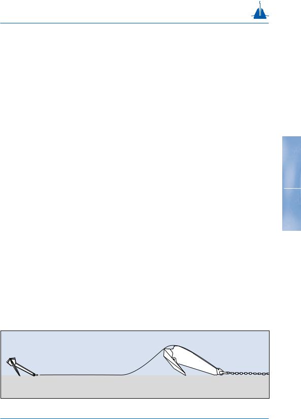
Since there is little difference between handling one hinging anchor or two, the first method is described with a Stevin anchor (hinging) in combination with a Stevpris anchor (non-hinging).
Here, the Stevpris is main anchor and the Stevin is back-up. This is the best solution when using a fixed shank anchor as the fluke of the Stevpris anchor can not be pulled closed. The pendant line is connected to the padeye near the anchor shackle so performance is not reduced.
Note: if the piggy-back anchor can not be laid in line with the mooring load, the piggy-back anchor makes the main anchor unstable. In such a case the Stevpris can better be placed as the second anchor.
For optimal performance of the combination, the |
75 |
pendant line between the two anchors should be wire rope, to promote penetration and obtain better holding capacity (fig. 3-60).
The installation procedure is described as follows:
•Pay out the main anchor as usual.
•Tension the mooring line until the anchor slips.
•Connect the second anchor to the pendant line.
•Bring the anchor to its location.
•Lower the piggy-back anchor and tension the mooring line again.
•Provide the pendant of the second anchor with a buoy for easy retrieval.
fig. 3-60

Piggy-back methods
Piggy-backing with two Stevpris anchors
When two Stevpris anchors are used in piggy-back, the holding capacity of the combination may be equal or higher than the sum of the individual holding capacities of the anchors. The installation procedure of two Stevpris anchors in piggy-back (fig. 3-61) is as follows:
•Pay out the main Stevpris anchor, with the mooring line connected to the anchor shackle and the pendant line (wire rope for optimal performance and approximately three times the shank length of the first Stevpris anchor) connected to the padeye behind the anchor shackle.
•Connect the other end of the pendant line to the anchor shackle of the second Stevpris anchor.
•To lower the second Stevpris anchor to the seabed,
76a second pendant line is connected to the padeye behind the anchor shackle.
•Using the second pendant line, the Stevpris anchors are lowered to the seabed and positioned and buoyed off.
•The Stevpris anchors are then tensioned by pulling on the mooring line (fig. 3-62).
fig. 3-62 |
fig. 3-61

Piggy-back methods
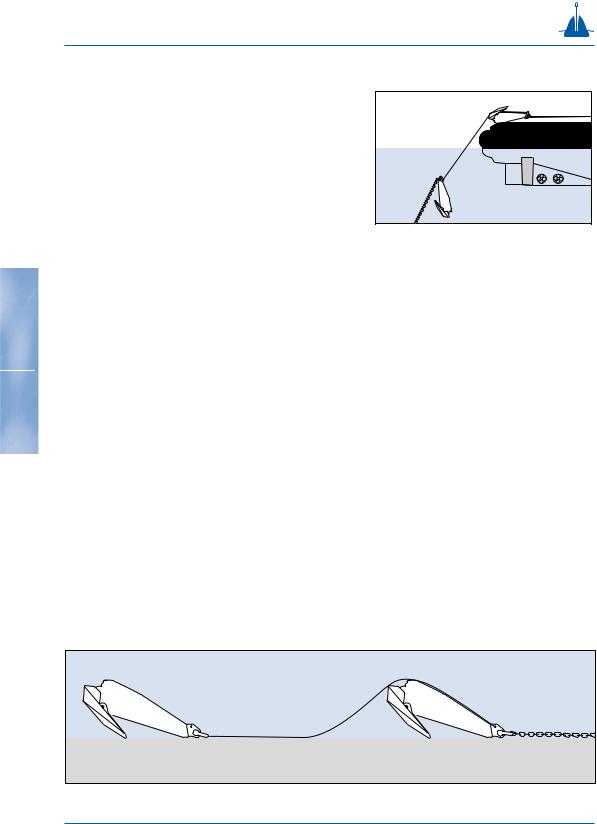
Piggy-backing by using a chaser
Sometimes chasers are used to connect the piggyback anchor to the first anchor (fig. 3-63), although a pendant line connected directly to the padeye behind the main anchor shackle of the first anchor is prefered.
The installation procedure described for two Stevpris anchors is also applicable when a chaser is used for the connection.
During the deployment of the piggy-back combination, care must be taken that anchors are installed in line with the load.
77
fig. 3-63