

- •Introduction to the Anchor Handling Course
- •Technical Specifications:
- •Winch Layout:
- •Power Settings / Bollard Pull
- •All operations on board must be performed in accordance with Company Procedures.
- •Risk Assessment
- •Planning
- •Planning:
- •Goal, example:
- •What to do:
- •Electrical winches
- •Winch operation
- •General Arrangement
- •A/H-Drum at full Capacity
- •Over speed
- •Water brake
- •Band brake
- •QUICK & Full Release
- •Hydraulic Winches
- •Lay out (B-type)
- •Hydraulic winch, “B-type”
- •TOWCON
- •Instruction for use of Wire Drums
- •Changing of Chain Wheels (Wildcats / Chain Lifter)
- •TRIPLEX - SHARK JAW SYSTEM.
- •Operation
- •Maintenance and inspections
- •Safety
- •2. OPERATION:
- •QUICK RELEASE:
- •EMERGENCY RELEASE:
- •CONTROL PANEL
- •Marks for Locked on Hinge Link
- •2.2- OPERATION OF THE "JAW IN POSITION ACCEPT" LEVER:
- •2.3 OPERATION OF THE CONTROL PANEL AT EMERGENCY POWER.
- •3. ELECTRIC AND HYDRAULIC POWER SYSTEM.
- •3. 1. ARRANGEMENT OF SYSTEM.
- •3.2. FUNCTIONING OF QUICK RELEASE - JAWS ONLY.
- •3.3. FUNCTIONING OF EMERGENCY RELEASE
- •4.2 Test without Load.
- •4.3 Test with Load.
- •5. General Maintenance
- •5.1 Accumulators Depressurising
- •5.2 Shark Jaw Unit
- •5.3 Guide Pins Units
- •5.4 Hydraulic System
- •5.5 Electric System
- •6. Control Measurements / Adjustments.
- •6.2 Adjustment of inductive proximity switches on lock cylinders.
- •6.3 Adjustment of Pressure Switches for Lock Pressure.
- •7. Test Program – Periodical Control
- •7.2 Checking List – Periodic Control Mechanical / Hydraulic.
- •7.3 Checking List – Periodic Control Electrical
- •7.4 Testing without Load – Yearly Testing.
- •7.5 Load Test – Emergency Release – 5 Year Control.
- •“Mark on line !”
- •“Double set of Jaws, Pins and Wire lifter”
- •View from the bridge.
- •“JAW READY FOR OPERATION”
- •“JAW LOCK POSITION ACCEPTED”
- •KARM FORK – SHARK JAW SYSTEM.
- •Wire and chain Stopper
- •Inserts for KARM FORK
- •Martensite:
- •Recommendations:
- •1. THE BASIC ELEMENTS OF STEEL WIRE ROPE
- •2. STEEL WIRE ROPE CONSTRUCTIONS
- •3. SPECIAL STEEL WIRE ROPES
- •4. USE OF STEEL WIRE ROPE
- •5. SELECTING THE RIGHT STEEL WIRE ROPE
- •6. ORDERING STEEL WIRE ROPE
- •7. STEEL WIRE ROPE TOLERANCES
- •8. HANDLING, INSPECTION AND INSTALLATION
- •9. INSPECTION AND MAINTENANCE
- •10. ELONGATION AND PRE-STRETCHING
- •11. OPERATING TEMPERATURES
- •12. MARTENSITE FORMATION
- •13. END TERMINATIONS
- •14. SOCKETING (WIRELOCK)
- •15. DRUM CAPACITY
- •16. CLASSIFICATION AND USE OF STEEL WIRE ROPE
- •17. ROPES
- •18. CHAINS AND LIFTING COMPONENTS
- •19. TECHNICAL CONVERSION TABLES
- •SWIVEL
- •MoorLink Swivel
- •Pin Extractor
- •Socket Bench
- •Chains and Fittings
- •STUD LINK MOORING CHAIN
- •OPEN LINK MOORING CHAIN
- •KENTER JOINING LINKS
- •PEAR SHAPE ANCHOR CONNECTING LINK
- •DETACHABLE CONNECTING LINK
- •D’ TYPE JOINING SHACKLES
- •‘D’ TYPE ANCHOR SHACKLES
- •SHACKLES
- •JAW & JAW SWIVELS
- •BOW & EYE SWIVELS
- •MOORING RINGS
- •FISH PLATES
- •PELICAN HOOKS
- •SLIP HOOKS
- •‘J’ CHASERS
- •PERMANENT CHASERS
- •DETACHABLE PERMANENT CHAIN CHASERS
- •PERMANENT WIRE CHASERS
- •‘J’ LOCK CHAIN CHASERS
- •The way to break the anchor loose of the bottom is therefore:
- •Table of contents
- •Introduction
- •General
- •Mooring systems
- •Mooring components
- •History of drag embedment anchors
- •Characteristics of anchor types
- •History of vryhof anchor designs
- •Criteria for anchor holding capacity
- •Theory
- •Criteria for good anchor design
- •Aspects of soil mechanics in anchor design
- •Soil classification
- •Fluke/shank angle
- •Fluke area
- •Strength of an anchor design
- •Anchor loads and safety factors
- •Anchor behaviour in the soil
- •Proof loads for high holding power anchors
- •Anchor tests
- •Soil table
- •Practice
- •Introduction
- •Soil survey
- •Pile or anchor
- •Setting the fluke/shank angle
- •Connecting a swivel to the Stevpris anchor
- •Chasers
- •Chaser types
- •Stevpris installation
- •Laying anchors
- •Retrieving anchors
- •Anchor orientation
- •Decking the Stevpris anchor
- •What not to do!
- •Racking the Stevpris
- •Deploying Stevpris from the anchor rack
- •Boarding the anchor in deep water
- •Ballast In fluke
- •Chaser equilibrium
- •Deployment for permanent moorings
- •Piggy-backing
- •Piggy-back methods
- •Stevmanta VLA installation
- •Installation procedure
- •Stevmanta retrieval
- •Double line installation procedure
- •Stevmanta retrieval
- •Double line installation with Stevtensioner
- •The Stevtensioner
- •The working principle of the tensioner
- •Measurement of the tensions applied
- •Umbilical cable and measuring pin
- •Break - link
- •Duration of pretensioning anchors and piles
- •Handling the Stevtensioner
- •General tensioning procedures
- •Hook-up
- •Lowering
- •Tensioning mode
- •Retrieving
- •Supply vessels/anchor handling vessels
- •Product data
- •Introduction
- •Dimensions of vryhof anchor types
- •Proof load test for HHP anchors (US units)
- •Dimensions of vryhof tensioners
- •Proof load/break load of chains (in US units)
- •Chain components and forerunners
- •Connecting links
- •Conversion table
- •Mooring line catenary
- •Mooring line holding capacity
- •Shackles
- •Wire Rope
- •Wire rope sockets
- •Thimbles
- •Synthetic ropes
- •Mooring hawsers
- •Main dimensions chasers
- •Stevin Mk3 UHC chart
- •Stevin Mk3 drag and penetration chart
- •Stevpris Mk5 UHC chart
- •Stevpris Mk5 drag and penetration chart
- •Stevmanta VLA UPC chart
- •Introduction
- •Propulsion system
- •Propellers
- •Thrusters
- •Rudders
- •Manoeuvring
- •Current
- •Wind
- •Other forces
- •Turning point (Pivot point)
- •Ship handling
- •General layout Jack-Up drilling unit:
- •General information about a Semi Submersible drilling unit:
Stevpris installation
Chaser equilibrium
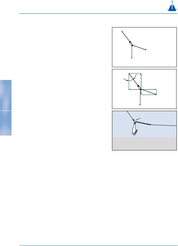
To control the anchor, the chaser collar must always be on the anchor head. The tension in the anchor cable must be equal or larger than 1.5 times the weight of the anchor. If not, the anchor slides through the chaser and the orientation is not controlled (fig. 3-54).
Equilibrium forces determine if chaser is in contact with the anchor. Near bottom, the vertical load at the chaser from the anchor line Flv is small. The chaser remains only in contact with the anchor if the bollard pull Fph is larger than the horizontal line load Flh which in turn must be larger than the anchor weight W (if not the anchor will slide down). The angle of the pendant line must be larger than 45° (fig. 3-55).
72
Recommendation: Bollard pull must always be equal or larger than the line tension, i.e. use a minimum bollard pull of 20 to 30 tons for a 12 to 15 ton anchor. Use a minimum pendant line length of 1.4 to 1.5 times the water depth in shallow water (100m) and 1.3 to 1.4 times the depth in deeper water (fig. 3-56).
pendant line force
anchor line tension
anchor weight
fig. 3-54
Fp |
Fpv |
|
Fph |
|
Flh |
|
|
|
|
Flv |
Fl |
fig. 3-55 |
W |
|
|
chaser |
|
fig. 3-56
Stevpris installation
Deployment for permanent moorings
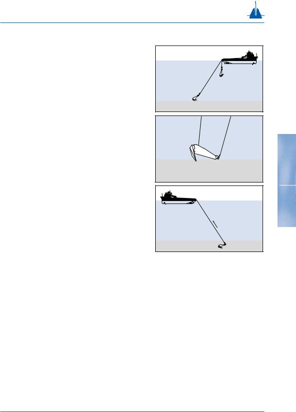
The simplest deployment procedure for the Stevpris anchor is to lower the anchor to the seabed using the mooring line. When the anchor is nearly on the seabed, the AHV should start moving slowly forward to ensure that the anchor lands correctly on the seabed (fig. 3-57).
Another option for the deployment of the Stevpris anchor is to connect a temporary installation bridle (wire rope) to the anchor. The bridle is connected to the padeyes situated at the back of the shank of the anchor. The AHV then lowers the anchor overboard while paying out the mooring line and the bridle simultaneously (fig. 3-58).
To recover a Stevpris anchor after it has been installed, the AHV should take the mooring line and pull it in the opposite direction that the anchor was installed in, generally away from the centre of the mooring. The AHV should recover the mooring line till a length of approximately 1.5 times the water depth is still overboard.
When only 1.5 times the water depth of mooring line is left overboard, the AHV should block the winch and keep a constant tension on the mooring line equal to the pre-load tension. Once the anchor starts to move in the soil, a lower tension in the mooring line can be used (fig. 3-59).
fig. 3-57
temporary bridle
mooring line
fig. 3-58
73
fig. 3-59