

Chasers
Chasers and their application
To facilitate handling, pendant wires may be applied to retrieve the anchor. These wires are connected to a pendant eye situated on the anchor and equipped with a buoy for picking up. In deeper water higher anchor break-out forces are encountered, resulting in longer, heavier pendant wires and consequently larger buoys. Due to wear caused by the continuous movement of the buoy by the waves, these pendants will break close to the buoy. The buoys would then float free and the anchors are much more difficult to recover.
To overcome this, chasers were introduced. These were rings ‘chased’ along the cable towards the anchor and back again to a rig or handling vessel.
58Their function was to ensure both installation and break-out of the anchor without having to use a pen-
dant line/buoy. The chaser system thus totally eliminates buoys, partly eliminates cables and reduces wear on the system.
The cost of a chaser is small when compared to the cost of a mooring line. It is therefore extremely important from an operator’s viewpoint that chasers do not inflict damage to the mooring lines.
Towing a chaser along mooring lines with, at times, high interface pressures, must result in wear. It is thus essential that such wear is taken by the chaser and not the mooring line. The chasers vryhof recommends are manufactured in a material that is softer than the steel used for the mooring line. Chaser wear is induced by the application of high interface pressure between the mooring line and the chaser. High interface pressure can arise from:
•Pulling the chaser along a slack mooring line.
•Maintaining high tension in the chaser workwire when chasing a tensioned mooring line.
Chasers
Chasing operations are best carried out on mooring lines which are fully tensioned. There is little need for the application of high interface pressure while chasing, the permanent chaser is captive on the mooring line and, unlike the J-chaser, will not become disengaged due to a slack work wire. For optimum chasing operations, the length of the chaser pendant line should be at least 1.5 times the waterdepth.
There are many different types of chaser available on the market today. A selection of the different chaser types is described in more detail on the following pages.
59
Chaser types
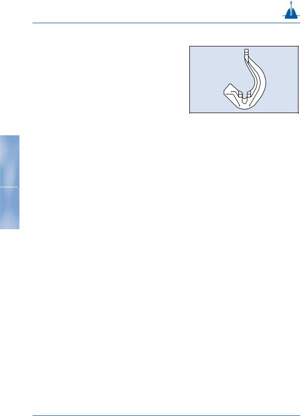
The J-lock chaser.
The J-lock chaser (fig. 3-19) has been designed so that it can slide along the chain in one direction and when the pulling direction is reversed, the chaser locks on the chain and does not slide any further. This means
that the tension in the mooring line can be wholly transferred from the rig to the chaser. The J-shape
permits catching the anchor chain after the anchor fig. 3-19 has been installed. This means that this chaser can be
used to assist in unforeseen circumstances. The wellbalanced and ‘guiding’ design of the chaser enables catching the chain when the chaser approaches a mooring at a point where the catenary angle is as high as 450.
When a normal permanent chaser is used under unfo-
62reseen conditions, there is the chance that the AHV cannot break out the anchor by means of the chaser.
The J-lock chaser can help in such an instance. It is released from a second AHV and slides along the chain towards the anchor. The design prevents the J-lock chaser from sliding back. The J-lock chaser is stopped at the permanent chaser. If the winch pull of both tugs is now increased, the J-lock chaser prevents the permanent chaser from sliding away from the anchor. Consequently, the forces required do not increase, and the anchor can easily be broken out. After this operation, the J-lock chaser can be released again.
This chaser can also be used when a very heavy chain has to be installed. It assists during installation by lifting the chain.