

TEKNISK INFORMATION |
10-27 |
Den elastiske forlængelse på ståltovet beregnes ud fra følgende formel:
Elastisk forlængelse (mm) = W * L / (E * A),
hvor: |
|
|
|
W |
= |
belastningen |
(kp) |
L |
= |
ståltovets længde |
(mm) |
E |
= |
E-modulet |
(kp/mm2) |
A |
= |
stålarealet |
(mm2) |
Hvis et mere præcist E-modul er nødvendigt, skal man måle E-mod- ulet på det aktuelle ståltov.
Varmeudvidelse
Et ståltov ændrer længde, når temperaturen ændres. Længdeændringen beregnes ud fra følgende formel:
Længdeændring (m) = a * L * Dt
hvor:
a = Lineære varmeudvidelseskoef. = 11 x 10-6 m/m pr. ° C i området 0° C til ca. 100° C.
L = Ståltovets længde (m).
Dt = Ændring af temperatur (° C).
Når temperaturen falder, bliver ståltovet kortere. Når temperaturen øges, forlænges ståltovet.
Forstrækning
Ved forstrækning belastes ståltovet indtil flere gange med ca. 45% af ståltovets nominelle brudstyrke, hvorved ståltovets sætningsforlængelse fjernes.
Fjernelsen af sætningsforlængelse forudsætter, at ståltovet ikke yderligere håndteres. Ved yderligere håndtering falder wiren mere eller mindre tilbage til dens oprindelige form, men forstrækning er i mange tilfælde alligevel en god ting, idet ståltovet væsentlig hurtigere stopper sin sætningsforlængelse. Dette medfører, at ståltovet ikke skal efterspændes så mange gange.
11. ANVENDELSESTEMPERATURER
Maksimum anvendelsestemperatur
· Zinken på galvaniserede tråde smelter ved 419° C. Ved 300° C begynder zinken at blive blød.
· En opvarmning selv på et relativt kort stykke af wiren til over 300° C - samtidig med at opvarmningen sker et stykke inde i wiren
- bevirker, at wiren kommer i ubalance og evt. låses. Tråd-/wirebrud opstår herefter hurtigere.
·Trådenes mekaniske egenskaber, f.eks. brudstyrke og bøjestyrke, ændrer sig ved opvarmning. Opvarmning i f.eks. en time ved 200° C bevirker et fald i trådenes bøjestyrke.
The elastic elongation in a steel rope is calculated according to the following formula:
Elastic elongation (mm) = W x L / (E x A) |
|
||
Where |
|
|
|
W |
= |
Load |
(kp) |
L |
= |
Length of steel wire rope |
(mm) |
E |
= |
Modulus of elasticity |
(kp/mm²) |
A |
= |
Steel area |
(mm²) |
If a more accurate Modulus of elasticity is required, it must be measured in the actual steel wire rope in question.
Heat Expansion
A steel wire rope will change its length when the temperature changes. Changes in length are according to the following formula:
Change in length (m) = a x L x Dt
Where:
a = linear heat expansion coefficient = 11 x 10-6 m/m per °C in area 0 to approx. 100° C.
L = Length of steel wire rope (m). Dt = Change in temperature (°C).
When the temperature drops, the steel wire rope will become shorter, whereas it will become longer if the temperature rises.
Pre-stretching
By pre-stretching, the steel wire rope is loaded to approx. 45% of its nominal tensile strength, during the course of which the steel wire rope's construction elongation is removed.
The removal of the construction elongation pre-supposes that the steel wire rope is not subjected to further treatment! If there is further treatment, the steel wire rope will more or less return to its original form. However, pre-stretching is in many cases a good idea anyway as it means that the steel wire rope more rapidly ceases its constructional elongation.
However, in many instances pre-stretching can still be beneficial, as the steel wire rope's constructional elongation will thus be completed much more quickly. This in turn means that the steel wire rope does not need to be re-tightened many times.
11. OPERATING TEMPERATURES
Maximum Operating Temperature
·Zinc on galvanised wires melts at 419 °C. At 300 °C the zinc begins to soften.
·If a relatively short piece of cable is heated to more than 300 °C, the heating affects the inside of the wire rope, the wire rope will become unbalanced and may become locked, causing fractures in the cable/wires to occur more quickly.
FKU LIFTING A/S |
Randers |
Odense |
København |
10 |
|
89 11 12 89 |
63 96 53 00 |
43 73 35 66 |
Jan 2002
TEKNISK INFORMATION |
10-28 |
·Et kunstfiberhjerte begynder at blive blødt ved 80° C - 100° C. Et blødt hjerte bevirker, at understøtningen for dugterne forsvinder og stålwiren kommer i ubalance. Tråd-/wirebrud vil hurtigere forekomme.
·Sisalhjerter kan tåle væsentligt højere temperaturer end ståltov med kunstfiberhjerte.
Da brudstyrke og bøjelighed/fleksibilitet ofte er vigtige mekaniske egenskaber for et ståltov, kan Randers Reb ikke anbefale, at:
·Ståltov med stålhjerte opvarmes til over 200° C gennem længere tid.
·Ståltov med sisalhjerte opvarmes til over 200° C gennem længere tid.
·Ståltov med kunstfiberhjerte opvarmes til over 75° C gennem længere tid.
Overfladetemperaturen kan i en kort periode accepteres at stige til 400° C.
Minimum anvendelsestemperatur
Stålet, der anvendes i ståltovet, kan anvendes ned til meget lave temperaturer (minus 200° C evt. lavere), uden at stålets egenskaber forringes væsentligt. Derimod vil olie/fedt ved minus 25° C - 50° C miste sin smørende og rustbeskyttende virkning. Desuden vil fiberhjerter let kunne knuses ved lave temperaturer.
Forudsat at stålwiren ikke indeholder fiberhjerter og at eventuelt olie/fedt ikke skal rustbeskytte og/eller have en smørende virkning, kan ståltovet anvendes ned til ca. minus 200° C. I modsat fald ned til ca. minus 25° C.
·The wires' mechanical properties, e.g. tensile strength and bending strength, change when the temperature rises. A temperature of e.g. 200 °C for 1 hour will reduce the wires' bending strength.
·An artificial fibre core starts to soften at 80-100 °C. A soft core means that the support for the strands disappears and the steel wire rope will become unbalanced, causing fractures in the cable/wires to occur more quickly.
·Sisal cores can tolerate significantly higher temperatures than steel wire rope with artificial fibre cores.
Since tensile strength and pliability/flexibility are often important mechanical properties for a steel wire rope, Randers Reb does not recommend that a steel wire rope with:
·A steel core is subjected to temperatures above 200 °C for a longer period of time.
·A sisal core is subjected to temperatures above 200 °C for a longer period of time.
·An artificial fibre core is subjected to temperatures above 75 °C for a longer period of time.
For a short period of time it can be acceptable for the surface tem perature to reach 400 °C.
Minimum Operating Temperature
The steel that is used in steel wire rope can be used at extremely low temperatures (minus 200 °C or less) without any significant effect on the characteristics of the steel. However, at temperatures of only minus 25-50 °C oil and grease will lose their ability to serve as lubricants and protect against rust. This makes the fibre cores easy to damage.
Provided that the steel wire rope does not have a fibre core and that oil and grease are not required as protection against rust or as lubrication, such rope can be used in operating temperatures of approx. minus 200 °C. If these conditions cannot be met, the minimum temperature is approx. minus 25 °C.
FKU LIFTING A/S |
Randers |
Odense |
København |
10 |
|
89 11 12 89 |
63 96 53 00 |
43 73 35 66 |
Jan 2002
TEKNISK INFORMATION |
10-29 |
12. MARTENSIT
Martensitdannelse
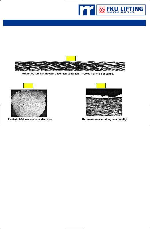
Martensit er en strukturændring, der sker i trådmaterialet ved høj friktionsvarme (se fig. 45) som f.eks. ved dårlig spoling på spil, hvor de yderste ståltovslag presses ned i de underliggende lag under en sådan belastning, at gnistdannelse opstår med efterfølgende hurtig
afkøling (se fig. 46).
Fig. 45
12. MARTENSITE FORMATION
Martensite formation
Martensite is a structural change in the wire material caused by a very sudden cooling of the rope after a strong local heating generated by friction. The friction may be caused by e.g. bad winding of the wire rope on winches.
Martensite spots in fishing rope which has been used under bad conditions
Fig. 46 |
Fig. 47 |
Flattened wire showing martensite structure
Denne strukturændring giver en hård men skør overflade, og under normal belastning eller ved splejsning kan trådbrud opstå, selvom der ikke har været nævneværdigt ydre slid (se fig. 47).
Forholdsregler mod martensitdannelse:
·Blokkene må ikke være nedslidte og bør kunne dreje let.
·Spoling på tromlen bør ligge i tætte vindinger uden krydsninger, så det overliggende lag under belastning ikke skærer sig ned i de underliggende lag.
·Ståltovet bør eftersmøres, således at friktionen mellem tråde og dugter er mindst mulig.
·Kontrollér ståltovet for sammentrykninger, små revner og mekaniske skader, som kan være tegn på martensitdannelse.
Hvis en stålwire er strømførende, eller ståltovet spoles op i flere lag under stor belastning, vil der ofte opstå gnister. Overfladetemperaturen, hvor gnisten opstår, er over 800° C, hvorfor sandsynligheden for dannelse af martensit er relativ stor. Hvis forekomsten af gnister er stor, opstår der hurtigt trådbrud og evt. wirebrud.
The brittle layer of martensite shows clearly
The martensite structure is very brittle and may cause fractures during normal operation or when spliced, even though the wire rope does not show any visible signs of external wear.
Precautions against martensite:
·The blocks must not be worn down and should turn easily.
·When a wire rope is wound on a drum, it should be in tight wraps without the layers crossing each other in order to prevent the top layer from cutting into the underlying layers.
·The wire rope should be lubricated at regular intervals in order to minimise the friction between wires and strands.
·The wire rope should be checked at regular intervals for crushing, minor cracks and mechanical damages, all of which might indicate martensite spots.
If a steel cable carries a current, there will often be sparks. The surface temperature where the sparks appear will be over 800 °C, making it quite probable that Martensite will be formed. If there is a strong probability of sparks appearing, wire and cable fractures may occur quickly.
FKU LIFTING A/S |
Randers |
Odense |
København |
10 |
|
89 11 12 89 |
63 96 53 00 |
43 73 35 66 |
Jan 2002
|
|
TEKNISK INFORMATION |
10-30 |
|||||||
13. ENDEBEFÆSTIGELSER |
|
13. END TERMINATIONS |
|
|||||||
Endebefæstigelser. |
|
End terminations |
|
|||||||
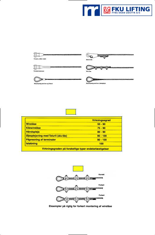
I fig. 48 ses eksempler på endebefæstigelser. |
|
Type of end terminations. Degree of efficiency |
|
|||||||
|
|
|
Fig. 48 |
|
|
|||||
|
|
|
|
|
|
|
|
|
|
|
|
Wire rope socket, resin poured |
|
|
|
|
|
|
|
|
|
|
|
|
Wedge socket |
|
|
|
||||
|
|
|
|
|
|
|
|
|||
|
|
|
|
|
|
|
|
|
|
|
|
|
|
|
|
|
|
|
|
|
|
|
Wire rope socket, swaged |
|
|
|
|
Clips |
|
|
|
|
|
|
|
|
|
|
|
|
|||
|
Mechanical splice with thimble and Talurit |
|
|
|
Hand-spliced with thimble |
|
||||
Eksempler på endebefæstigelser på ståltove
Examples of end terminations on steel wire ropes
En endebefæstigelse nedsætter normalt brudstyrken på ståltovet. Tabel 6 angiver virkningsgrad (tilnærmet) for de forskellige typer endebefæstigelser.
End terminations normally reduce the tensile strength of steel wire rope. Table 6 shows the approximate effect of the different types of end terminations.
Tabel 6
Clips
Wedge socket
Hand-spliced
Mechanical splice with ferrule
Wire rope socket, swaged
Wire rope socket, resin poured
Degree of efficiency for different types of end terminations
Fig. 49 viser eksempler på rigtig og forkert montering af wirelås.
Fig. 49 Examples of correct and incorrect attachment of wire rope clips.
Fig. 49
Right way
Wrong way
Wrong way
Examples of correct and incorrect ways of attachment of dead end on different kinds of wedge sockets
FKU LIFTING A/S |
Randers |
Odense |
København |
10 |
|
89 11 12 89 |
63 96 53 00 |
43 73 35 66 |
Jan 2002