for some Ω so(m), then the solution of u is of the form u(t) = U (t)u(0)
for some U (t) SO(m). Prove this assertion.
7.Proposition 8.4 gave a formula for the first derivative of the optimal inputs. Use the method of the proof of that proposition to obtain a formula for u¨. Express the answer in terms of Lie brackets of the input vector fields. In fact, if you are adventurous, try to find the formula for u(n).
8.Use the results of Proposition 8.16 to show that the optimal input of that proposition normalized by ku(0)k, that is,
u(t)
ku(0)k
solves the minimum time steering problem to steer the system from q(0) = q0 to q(T ) = qf subject to the constraint that ku(t)k2 ≤ 1 for all t.
9.Apply the methods of Proposition 8.16 to solve the optimal control inputs for the model control system we studied in Section 2, namely
q˙1 = u1 q˙2 = u2
q˙3 = q1u2 − q2u1.
10.Extend the method used to find the optimal inputs for Engel’s system to find optimal inputs for the system of Exercise 2.
11.Consider the least squares optimal input steering problem for a system with drift:
m
X
q˙ = f (q) + gi(q)ui.
i=1
(a)Find the expression for the optimal Hamiltonian and prove that the optimal inputs satisfy the di erential equation
pT [f, g1]
|
pT [f, gm] |
|
u˙ = Ω(q, p)u = |
|
. |
|
(8.38) |
|
|
. |
|
|
|
|
|
|
with Ω(q, p) defined as in (8.16).
393

(b)Find the second derivatives of the optimal inputs given in equation (8.38).
12.Consider the following system
q˙1 = u1 q˙2 = u2 q˙3 = q2u1
with initial condition q(0) = 0. Let the inputs be of the form
u1 = α1,0α1,1 cos 2πt + α1,2 sin 2πt
u2 = α2,0 + α2,1 cos 2πt + α2,2 sin 2πt.
(a)Integrate the control system symbolically from t = 0 to t = 1 to obtain q(1) as a function of α, the coe cient vector of the inputs, and compute the Jacobian A = ∂q∂α(1) R3×6.
(b)Prove that if A is full rank then the system is controllable with inputs of the above form.
13.Consider the one-chain system in equation (8.7). For the Philip
Hall basis g1, g2, adkg1 g2, k = 1, . . . , n − 1, derive the Chen-Fliess- Sussmann equation.
14.Consider the following system
q˙1 = u1 q˙2 = u2
q˙3 = q1u2 − q2u1 q˙4 = q12u2.
(a)Derive the Chen-Fliess-Sussmann equation.
(b)Assuming that the inputs are of the form
u1 = a0 + a1 cos 2πt + a2 sin 2πt u2 = b0 + b1 cos 2πt + b2 sin 2πt,
compute the polynomial equation for the amplitude parameters in terms of the initial and final states.
Chapter 9
Future Prospects
In this book, we have tried to give the reader a feel for the sorts of analytical tools that one needs in the study of robotic manipulation. We have adopted a mathematical point of view because of its compactness. One thing that this mathematical point of view masks is the excitement that we feel for robotics technology and its future because of the considerable innovation and the development being made in its use. The robotics industry has reached one plateau with the successful introduction of robots into automotive manufacturing—spot welding and painting are two arenas where robotic usage is almost universal, assembly of engines is an area where the amount of utilization is more varied—and into electronic assembly. There are several other areas where the usage of robotics is in its infancy and this chapter is dedicated to brief descriptions of some of these fields along with a quick assessment of their current status.
One question that comes up often in such a retrospective is the di erence between “teleoperation” and “robotics.” While precise definitions and distinctions between these two topics are elusive, the rough distinction appears to be in the amount of human interaction: “human intelligence” rather than “machine intelligence” required for the operation of the same set of basic devices. Consequently, it hardly seems surprising to us that in the natural course of evolution of the technology, teleoperation will precede true robotic or autonomous operation. Indeed, the pragmatic point of view would be to favor the introduction of new robotic devices first in teleoperated form. This has also historically been the path of evolution of the field. Nonetheless, there are good reasons for not having a person in the feedback loop in many applications:
1.Communication delays in transmission of sensor information and receipt of command information
2.Slow speed of response of humans to numerical and quantitative data
In our opinion, the teleoperators of today are the autonomous robots of tomorrow and as such we will not make a distinction between them in this chapter.
One other topic that comes up a great deal in the popular science press is the concurrent usage of the terms virtual reality, and telepresence. The term virtual reality refers to the remote creation of a synthetic environment containing sights, sounds, touch, and forces. While remote sight and sound are easily implemented, remote touch and force are not as easily achievable. In order to manipulate objects remotely (telepresence), it is important to be able to have each of these senses. Thus, there is an intimate relationship between remote manipulation or telepresence and virtual reality. Indeed, we see that the bulk of the current literature on virtual reality is really about telepresence, since the purpose of simulating a remote environment is to allow a person to interact with it.
In summary, we feel that the technological progress in the years to come will be on a broad front spanning teleoperation, virtual reality, and dextrous manipulation. In the rest of the chapter, we will say a little bit about the opportunities. The sections are organized according to the scale of the robots: Section 1 deals with conventionally sized robots, Section 2 with robots at the millimeter scale, and Section 3 with robots at the micrometer and nanometer scale.
1Robots in Hazardous Environments
One of the chief areas for the future (and current) use of robots of the conventional size is in hazardous environments. In this section, we give a brief description of the sorts of environments in which robots will be (and are) found.
Space
The best known example of a robot in space is the 20 meter long remote manipulator system on board the space shuttle. It has six degrees of freedom and is usually manually teleoperated by an astronaut under direct visual feedback. There is, however, the ability to have the robot be moved under computer control in Cartesian coordinates. There are Japanese plans to build a flight telerobotic servicer which has two cooperating robot arms for repairing satellites and other coordinated activities on board a self-propelled platform. Other examples of robots in space include the Mars rover and other planetary exploring robots which feature tracked or wheeled mobile bases with arms on board for scooping soil samples. It is not anticipated that these devices will be under human control remotely since the transit time delays for commands are too high to allow for meaningful remote feedback actions.
Underwater
In the last decade, several remotely-operated vehicles have been built for inspection of underwater oil derricks and exploration. Their development has been motivated by the high cost of human divers and the risk to life of working under water. For the most part they consist of a mobile platform, either on an umbilical line from the mother ship or completely autonomous, fitted with one or more robotic arms. Most of these robots are remotely piloted and most current undersea manipulators are hydraulic to withstand the high forces and corrosive elements that they need to withstand. In the future, there will be a surge in the number of completely autonomous robots for exploration of the ocean floor and other unstructured environments for which the human reaction time is too large.
Nuclear, toxic waste disposal and mining
Some of the earliest work in robotics came from teleoperators for handling radioactive material. In recent years mobile robots with robotic arms onboard for inspection, maintenance, and even for handling of spent fuel rods, have become more prevalent. With the growth in the extent and nature of hazardous materials that need to be disposed worldwide, robots for handling and disposing toxic materials will need to be developed. Mining environments are similarly hazardous and there are already quite a few di erent kinds of mining vehicles and arms that can be remotely operated.
Firefighting, construction and agriculture
One can visualize a scenario in which maps of buildings would be downloaded onto robots at the scene of a fire. These robots can then be used for firefighting using onboard heat and smoke detectors and trailing an umbilical cord carrying water as well as fire-retardant chemicals and relaying video data to remote locations. In this application, it seems important to have robots that can negotiate stairways as well as corridors (i.e., legged as well as wheeled robots). Automated construction is a field in its infancy, but robotic tools for accurate and risk-free construction, sometimes in underground or underwater environments, are developing rapidly. In agriculture, multifingered robot hands mounted on an arm and equipped with vision systems have been used for picking oranges and for harvesting crops. It is thought that robots could also be used for tilling and planting.
Robotic systems have also been used for deboning meat in meat packing plants in Australia. Finally, an amazing robotic system that has been used for sheep shearing has been developed at the University of West Aus-
tralia and features the development of a wrist with no singularities in the workspace of the manipulator [114].
2Medical Applications for Multifingered Hands
In recent years, there has been a great deal of excitement about minimally invasive surgery, including a number of techniques for accessing internal organs through small incisions or orifices in the body (varying in size from about 3 millimeters to 11 millimeters). As a result, trauma to muscles and other tissue which need to be cut in traditional surgery is minimized, resulting in a considerable savings in recovery time, risk to life during the operation and hospital stay. Typically, in these procedures, slender probes are introduced via a puncture and tools such as probes with laser light sources, cameras, and instruments are fed into the body cavity. In some cases, the body cavity is distended with gas (usually the abdominal cavity) to create viewing room. The advances in active optics (CCD imagers and high resolution displays) and fiber optics have made it possible for the surgeon to have very high quality images of the inside of the body through a small aperture. Several instruments can then be used to take advantage of this vision of the inside of the body cavity: the endoscope is used for the inside of the gastro-intestinal tract, the laparoscope for the abdominal cavity, the thoracoscope for the thoracic cavity and the arthroscope for the inside of the joints. Several procedures, such as the removal of the gall bladder (cholecsystectomy) using the laparoscope, removal for biopsy of polyps in the gastro-intestinal tract using the endoscope, repairing hernias in the lung cavity using the thoracoscope, and scraping away scar tissue in the knee joint using the arthroscope, are now commonplace. Of the 600,000 cholecsystectomies performed annually in the U. S. it is thought that up to 500,000 are performed laparoscopically and, according to some practitioners, minimally invasive techniques will dominate “open” surgery in the future.
However, what limits minimally invasive surgery is manipulator technology, for the following reasons:
1.Inadequate degrees of freedom. Current needle holders, cutters and other tools transmit a surgeon’s hand motion through passive mechanisms. Further, tactile feedback is disrupted. Foremost among the limitations imposed by today’s tools is their limited number of degrees of freedom. For example, a needle driver that can slide, twist and pivot (up and down as well as left and right) inside the body cavity gives a surgeon only four degrees of freedom without full control of orientation. Thus, suture lines must radiate from the insertion point, since the needle can only be driven by twisting the driver about its long axis.
2.The need for fine motion control in surgery. In open surgery the surgeon braces herself so as to reduce the amount of tremor transmitted to the end of the surgical device. In the instance of minimallyinvasive surgery, the fulcrum at the point of entry of the instrument reduces the tremor for pivoting motions of the tool, but does not help positioning accuracy in the other directions caused by shoulder and elbow tremor.
Improved manipulators with many degrees of freedom would increase e ciency, safety, and the range of cases that could utilize these methods by addressing the drawbacks mentioned above. However, the kinematics of useful devices is complex for many reasons. To realize the gains of minimally invasive surgery, we feel that the technology of multifingered robot hands could be brought to bear. The design, construction, and control of a miniature hand-like manipulator requires significant departures from more traditional robot manipulators. Because of the small sizes of the fingers (on the order of millimeters), direct actuation of each rotary or prismatic joint is not practical. In some of our own preliminary work, we have constructed small fingers which are either controlled by cables or by small hydraulic actuators. The fabrication techniques for the manipulator are borrowed from integrated circuit technology. Although common metal and plastic materials are capable of developing biologically significant forces at this small scale, it is a challenge to develop actuators which exhibit large enough ranges of motion.
At the outset, teleoperator technology which is used to reflect the actions of the surgeon into the body cavity will be used to control the surgical manipulators. User interfaces such as sensor gloves worn by the surgeon would provide the surgeon with tactile and force feedback, while the positioning of the fingers would be measured by sensors and transmitted to small multifingered hands. One such system has been proposed by us in [19].
The growth potential of this application is enormous. Remote surgery is being explored for use on the battlefield and in space, and with greater intelligence, control, and sensing built into surgical manipulators, one can conceive of surgical workstations in the not too distant future.
3Robots on a Small Scale: Microrobotics
In many new applications, it is necessary to handle or manipulate very small objects, for example living cells or parts of semiconductor electronics. The scale of operations that we visualize in these applications are several orders of magnitude smaller than those involved in the surgical applications of Section 2, which we have termed milli-robots. Thus, in this section we will concentrate on microand nano-scale robots. There
are two di erent approaches to dealing with these small objects: the first to use a conventional (large) manipulator with a very precise control system and the second is to miniaturize the manipulator. There are many advantages to shrinking the robots to the same scale as the parts being manipulated:
1.Delicate forces can be applied.
2.Robots can be made more accurate.
3.Robots can be fabricated using silicon processing and photolithographic techniques.
The notion of a micro-robot on a chip has been popularized by Brooks and Flynn [16] and Pister, Fearing, and co-workers [91, 92, 93]. We foresee a scenario in which these robots see wide application in micro-teleoperation in cramped areas, and in massively parallel handling of small biological and electromechanical systems. In this section, we abstract from Fearing [31] some of the technological challenges and opportunities in this rapidly growing area.
There are many engineering issues to be addressed in building microrobotic systems: the power source, the propulsion method (if they are mobile), control integrated with sensing, and communications with the macro-world. One key new technology that provides new capabilities for sensing and actuation at the micro scale is micromachining. This is the ability to machine at very small scales, including the micron scale, using techniques from integrated circuit fabrication. This can be used, for instance, to produce actuators which have hundreds of miniature cilia (like a paramecium); or to make mechanisms like grippers that can handle parts of the size of 10µ diameter or planar rotary motors of a few microns size and sensors like miniature gyroscopes. At these sizes, forces scale di erently so that electrostatic forces are stronger than electromagnetic forces. This necessitates a rethinking of actuation methods for these mechanisms.
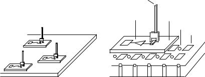
Intelligent sensors, actuators and control systems can be integrated on a single chip. A novel integrated system for manipulating dry parts in the plane was proposed by Pister et al. [92]. This system consists of a 1 cm2 silicon substrate with an air bearing to support individual 1 mm2 platforms. The individual platforms are driven in the plane by electrostatic forces and can carry grippers, probes for sensing, or tools for processing. Capacitive position sensing of the platforms is added to complete the system. This system has been partially fabricated and a conceptualization of it is presented in Figure 9.1. It was designed in analogy to macro-robot manipulator called Robotworld (made by Automatix Corporation) and was made to automatically align and splice together fiber optic cables.
Current micro-mechanical systems are for the most part planar. However, it is clear that for manipulators to extend far beyond the surface
|
|
.. |
|
|
. |
. . |
|
|
. |
. |
|
. .. |
|
. |
|
.. |
|
. . |
|
|
|
|
. . |
|
.... . |
|
.... . |
|
|
Probe
|
s. . |
|
|
|
Sensing circuitry |
Platform |
|
|
|
|
|
. . |
|
Air hole |
|
|
|
Electrode |
? |
... . |
? |
|
? |
|
|
? |
Figure 9.1: (a) View of several probing platforms floating on the same bearing surface. (b) Detailed view of a single platform. (Figures courtesy of Kristofer Pister and Ronald Fearing)
that they are mounted on, it is important to have 3-D structures. A promising new approach in this regard is the micro-hinge method of Pister et al. [93]. This approach consists of actually fabricating components in 2-D, but providing them with the ability to rotate or slide into place resulting in the assembly of a 3-D structure. By using techniques drawn from origami, the Japanese art of paper folding, the structures can be made to self assemble under agitation in a water bath after emergence from the silicon foundry.
In the years to come we feel that there will be an explosive growth of micro-machined robots with propulsion capabilities in fluids and with onboard robots and multifingered robots for manipulation so as to do a variety of tasks both on the biological and integrated circuit fronts.