

Therapeutic Micro-Nano Technology BioMEMs - Tejlal Desai & Sangeeta Bhatia
.pdfFIGURE 19.1. Cells respond to a variety of local, dynamic physichochemical signals, either from their fluidic environment, their cell neighbors, or their underlying substrate.
FIGURE 19.2. Central elements and limitations of cell culture technology. Cell culture is essentially based on the immersion of a monolayer of cells in a homogeneous bath, using costly human labor, bulky equipment, and large numbers of cells, supplies, and fluid volumes.
FIGURE 19.3. A combinatorial micromixer that allows for generating all the 16 mixture combinations of 4 dilutions of blue dye (left side of the device) and 4 dilutions of orange dye (right side of the device). Flow is from top to bottom. The outlet channels are 1 mm wide and 100 μm deep.
CELL BIOLOGY ON A CHIP |
349 |
plates and fluid delivery steps grows geometrically as the number of cell culture parameters increases. For example, the very optimization of a defined cell culture medium (for a particular cell type, a particular application, and even a particular phenotype), which may involve studying the non-linear, non-additive effects of various hormones, growth factors, aminoacids, glucose, salts, etc. at different concentrations, as critical as it can be for the success of an experiment, can become a monumental task in its own that only a few cell culture laboratories can afford to undertake. As cell culture studies become increasingly sophisticated, the development of fast, inexpensive mixers that generate a combinatorial range of fluid mixtures becomes imperative. Previously, several groups have reported micromixer designs that generate microfluidic dilutions. Dertinger et al. [44] have demonstrated a symmetric two-dimensional (2D) microfluidic network that continuously generates certain combinations of dilutions of two compounds, although not all the combinations are possible because mixing and dilution are not independent. Independent mixing and dilution clearly require three-dimensional (3D) networks [45, 46] that allow channels to pass over one another. Ismagilov et al. [47, 48] have demonstrated orthogonal microchannel arrays that create a potential mixing point at every channel intersection. Another 3D device converted four inlets (A, B, C, D) into four undiluted binary mixtures (AC, AD, BC, BD) [49]. However, none of these devices allowed for combinatorial mixing of all the dilutions of the input compounds. Another design dilutes and mixes stationary fluids in microchambers connected by valves [50, 51]. We have devised a microfluidic mixer design that produces all the mixture combinations of four dilutions of (two) input compounds and delivers the sixteen mixture combinations in separate outlet microchannels (Fig. 19.3). The device features four different flow levels made by stacking nine laser-cut Mylar laminates. The fluidic network has a symmetric design that guarantees that the flow rates are nearly identical at all the outlets. Such systems should find uses in cell-based combinatorial screening.
19.3.2. From Incubators to “Chip-Cubators”
Cell culture equipment—comprising at least an incubator (required to preserve temperature, humidity, and gas concentration of the cell culture medium) and a tissue culture hood (required to preserve sterile conditions)—is expensive and bulky; usually, a dedicated room is recommended. Culturing cells in closed, microfluidic chambers circumvents the need for constant-humidity systems, however it also calls for the development of gas exchange and temperature control systems on chip if the miniaturization of the cell maintenance equipment is to be fully realized. Although seemingly trivial from an engineering point of view, the full miniaturization of a cell maintenance system is yet to be achieved; this may reflect not so much its technical difficulty but the fact that such a system has a small payoff for the average researcher, who still needs the traditional cell culture room for intrinsically “bulky activities” such as primary cell isolation and expansion of cell lines. Relatively small (yet macrofluidic) perfusion chambers featuring incubation capabilities for long-term live cell (e.g. time lapse) microscopy are commercially available.
19.3.3. From High Cell Numbers in Large Volumes (and Large Areas) to Low Cell Numbers in Small Volumes (and Small Areas)
A typical cell culture experiment uses large numbers of cells, which results in substantial animal suffering—an increasing concern in our society—and supplies (the culture surfaces
350 |
ALBERT FOLCH AND ANNA TOUROVSKAIA |
as well as the fluids); this results in expensive experiments that take a lot of bench or incubator space. When the cultures are used for harvesting certain biochemicals, the need for large numbers of cells is most often not intrinsic to the experiment but mostly due to the need for collecting high concentrations of the biomolecule of interest (e.g. a cell-secreted product, DNA or mRNA content) and/or the need for collecting high volumes if the assay so requires (e.g. centrifugation, filling a well of a 96-well plate). In a microfluidic culture, compared to a traditional open-dish culture, both the area occupied by the cells and the volume bathing the cells are scaled down, but the volume can be (and typically is) scaled down by a larger factor than the area because of the reduced height of the fluid. Aside from considerations on the constancy of the cell culture environment (which will be addressed below), this means that, in microfluidic cultures compared to their non-microfluidic counterparts, the collected concentrations are higher (which contributes to increase the signal-to-noise ratio of the measurement), but the collected volumes are smaller (which often makes the fluid collection and the detection more challenging); thus, depending on the sensitivity of the assay, the microfluidic collection of fluids for use in a macrofluidic assay may not be beneficial nor practical, and a microengineered version of the assay may have to be developed. When possible, assays based on microscopic observation (e.g. calcium imaging using fluorescent markers, time-lapse imaging of changes in cell morphology), which can be done in situ, should prove more practical. However, microscopy assays have inherently low throughput (the microscope probes only a small field of view), so adopting a microscopy assay in a microfluidic cell culture hinders the high-throughput benefits of microfluidic perfusion; to achieve high throughputs, a programmable motorized stage can be used to automate image acquisition from multiple fields of view.
19.3.4. From Milliliters to Microliters or Nanoliters
A typical cell culture experiment also uses large volumes of reagents, some of which are extremely expensive (on the order of hundreds of dollars per microgram) and costly to dispose of. Microfluidic perfusion naturally requires smaller volumes and, as a result, is inexpensive compared to macrofluidic perfusion. In some cases, the benefits may not be huge; a macrofluidic culture can be stagnant (no medium change) for many hours, sometimes days, because the necessary nutrients, ions and gases required by the cell are amply drawn from the large volume of medium (typically on the order of a 1 mm-thick layer of fluid, or25 nL/cell for a confluent monolayer of cells, 100 cells/mm2), which contains enough nutrients and buffering capability to sustain a nearly-constant environment for periods up to 1–3 days. In contrast, in a microfluidic culture the fluid layer thickness and the volume per cell are typically one order of magnitude smaller. As a result, a microfluidic culture cannot be stagnant for long periods of time (depending on the cell density) because the cells rapidly acidify their environment and require a stable supply of nutrients and oxygen. Hence, long-term/dense microfluidic cultures may require frequent medium changes or continuous perfusion that can also consume large volumes if precautions are not taken to minimize the flow rate. The most convenient source of energy to drive flow is undoubtedly gravity (i.e. the inlet reservoir is placed higher than the outlet reservoir); however, given the high density of water, gravity-driven flow is not easily minimized, which results in accidental fluctuations and lack of reproducibility. We have achieved minimal flow rates of 1 mL/day for >7 days by placing the inlet(s) of fresh cell culture media lower than the outlet of the
CELL BIOLOGY ON A CHIP |
351 |
microchannel; a piece of paper tissue then pulls the fluid up the gravity slope from the outlet by capillarity (the fluid does not accumulate because it eventually evaporates from the wet paper surface). Long-term cultures are especially important in studies of cell differentiation, because many differentiation processes take several days to complete. As an example, our group is interested in studying how the microenvironment of muscle cells affects their differentiation. The central part of their differentiation program consists of fusing with each other to form multinucleated, tubular-shaped cells called myotubes; subsequently, the cells up-regulate the synthesis of acetylcholine receptors (AChRs), which end up forming clusters at the cell membrane through the action of agrin (in vivo, agrin is released by the nerve tip). The AChRs can be visualized by fluorescence microscopy after the cells are fluorescently labeled with α–bungarotoxin (BTX), a neurotoxin that blocks AChRs. In our efforts to control the microenvironment of myotubes, we seed C2C12 cells (a muscle cell line that is widely used as a model for myogenic differentiation) in microchannels and allow them to proliferate for a period of many days and subsequently fuse; importanly, the cells do not fuse unless their medium is switched to low-serum content after several days of serumcontaining medium. Fig. 19.4 shows a microfluidic muscle cell culture where all solution changes (from the first, for seeding, till the last, for the fluorescence assay) were done through the microchannel inlet. Fig. 19.4a shows C2C12 cells in a PDMS microchannel (on fibronectin-coated glass) 4 hours after seeding. The images in Fig. 19.4b (phase-contrast micrograph) and 19.4c (corresponding fluorescence image of BTX-labeled AChRs) were taken at day 7, after the medium had been switched to low levels of serum (which arrested their proliferation and prompted them to fuse); the clusters of AChRs in Fig. 19.4c indicate an advanced level of muscle cell differentiation. We note that Fig. 19.4c represents a fullymicrofluidic fluorescence assay, where the fixative and fluorescent labeling reagents were delivered via the microchannel. Minimization of the flow rate can be important not only to minimize reagent cost but also to minimize the area and volume taken up by the reservoir of fresh cell culture medium. Importantly, this long-term perfusion setup is simple and can be transferred to any biology laboratory equipped with a cell culture incubator.
19.3.5. From Manual/Robotic Pipetting to Microfluidic Pumps and Valves
Fluid metering is largely based on calibrated pipettes (volumes >1 μL); this approach is clearly not adequate for nanoliter (or smaller) volumes and has an extremely low throughput unless expensive robotic dispensers are used. In a microfluidic device, although the volumes of microchambers can be known with high precision, the measurement of flow rates is challenging because it requires specialized flow visualization techniques; as a result, continuous flow systems such as micromixers are not easily metered,. However, stationary volumes (e.g. microchambers closed by microvalves) are straightforwardly known independently (roughly) of their size and number. The volume of the chamber may be difficult to predict if the microvalve is of the “pinch-type” [52–54] (where the chamber is created by flattening a given section of a microchannel); furthermore, in these pinch-type valves, the microchannels must be fabricated with a rounded profile (a challenging geometry in microfabrication, usually produced by the “photoresist reflow” method), otherwise the microchannel does not flatten completely [54].
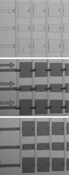
An alternative design [55, 56] employs a PDMS membrane but only deforms the chamber when it opens, returning to the original geometry when it closes (see Fig. 19.5 for an
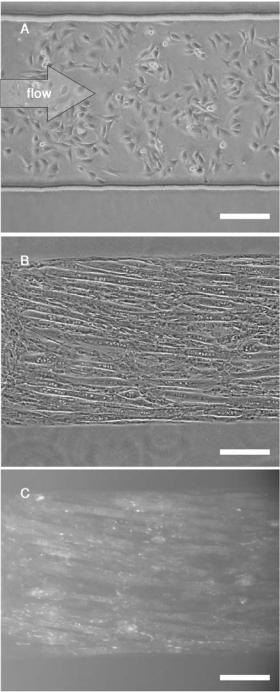
FIGURE 19.4. C2C12 cells cultured inside a PDMS microchannel. (A) phase-contrast image taken 4 hours after seeding. (B) Phase-contrast image taken after the cells have fused into myotubes and have been fixed. Note that the myotubes have aligned with the direction of the channel. (C) Fluorescence microscopy image of the same area as
(B) demonstrating a myotube-specific staining assay performed in the microchannels; the small bright spots reveal the presence of clusters of acetylcholine receptors (bound to fluorescently-labeled a-bungarotoxin), a marker for muscle cell differentiation. Scale bar is 50 μm.
CELL BIOLOGY ON A CHIP |
353 |
Empty device
Open valves
Closed valves
FIGURE 19.5. Elastomeric microvalves to control nanoliter-sized chambers. The largest chambers are 500 μm × 580 μm × 55 μm ≈ 16 nL, the smallest 6 nL in volume.
354 |
ALBERT FOLCH AND ANNA TOUROVSKAIA |
example). This geometry is more convenient for applications where the volume of the microchambers needs to be known with high accuracy: the shape of the microchambers is defined by photolithography and their height is given by the height of the photoresist layer. For example, the smallest chamber in Fig. 19.5 is 500 μm × 220 μm × 55 μm ≈ 6 nL; since it is possible to know the dimensions with an error of around 1% on each dimension, the volume can be known within approximately ±3% = ±20 pL.
19.3.6. Single-Cell Probing and Manipulation
In cell culture, both single-cell probing (e.g. “patch clamp” electrophysiological recordings [57]) and cell manipulation (e.g. oocyte handling, microinjection) are at present mostly based on glass micropipettes. While micropipettes are a powerful tool by virtue of the small size of their end apertures ( 1 μm or less in diameter for ion channel recordings), they require expensive vibration isolation equipment and micromanipulators (to gently approach the micropipette to the cell) and a considerable amount of manual skill and expert training, resulting in very low throughputs and high failure rates. Recently, a number of groups have reported microfluidic systems featuring arrays of micronor submicron-sized holes onto which the cells are deposited, potentially allowing for the automation of large numbers of “patch-clamp on a chip” measurements simultaneously [58–60]; some systems even feature micronozzles [61], with potential for highly parallel microinjection applications. As a gentler alternative to micropipettes for positioning single cells, focused “laser traps” [62] are being implemented but have an exorbitant cost and cannot be scaled up to manipulate large numbers of cells. Dielectrophoretic traps, on the other hand, can be actuated in parallel for separating, immobilizing and/or releasing large arrays of single cells in a microfluidic environment [63–67].
In summary, for the traditional cell culture user, the issues related to cost and throughput are practical and can, in principle, be overcome with increased resources or funding. Nevertheless, most cell biologists will compromise on the number of conditions (different factors, substrates, cell types) that would ideally be probed, resulting in poor statistics (particularly when obtaining single-cell data) and non-quantitative results; in such cases, the microfluidic implementation of a cell culture experiment represents a practical improvement that results in lower overall cost, higher throughput, and/or more quantitative/single-cell results. Very large increases in throughput may enable certain classes of experiments—such as statistically demanding ones—that would otherwise be impractical or too expensive to be addressed with traditional cell culture methods.
19.4. INCREASING THE COMPLEXITY OF THE CELLULAR MICROENVIRONMENT
The interest in miniaturizing the cell culture laboratory goes beyond the need for higherthroughput technology: it represents an enabling tool that allows the researcher to quantitatively control the microenvironment of the cell at the single-cell level and hence address biological questions which cannot be addressed (in a practical, statistically-meaningful manner) with present tools. Cellular processes such as adhesion, migration, growth, secretion, and overall gene expression are triggered, controlled, or influenced by the three-dimensional
CELL BIOLOGY ON A CHIP |
355 |
biochemical and biophysical architecture of neighboring surfaces. This organization cannot be, to the present day, straightforwardly reproduced in the laboratory, but many advances have been made in that direction. Below we review how microtechnology may aid in increasing the complexity of the cellular microenvironment and discuss the issues that may arise:
19.4.1. From Random Cultures to Microengineered Substrates
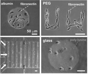
In traditional cell culture, cells are randomly seeded over the whole substrate; thus, cellular interactions that are strongly dependent on the proximity, distribution, and/or relative position of cells or biomolecules can become confounded by the presence of other, similar interactions. The advent of cellular micropatterning methods has offered the possibility of tailoring the cellular and biochemical neighborhood of cells with resolution down to single cells [68]. In the past, cell biologists have resorted to clever approaches to recreate different degrees of tissue organization in the laboratory. Harrison, for example, used spider webs to study cell migration as early as 1912 [69]. Others studied cell behavior on surface features such as milled grooves on mica [70], polystyrene replicas of diffraction gratings [71], polyvinylchloride music records [72], dried protein spots [73, 74], crystals [75], and scratches in agar [76], in phospholipid films [77], or in extracellular matrix protein [78]. Albeit ingenious, the technology utilized in these studies could not address the structural dimensions, chemical heterogeneity and/or precise repeatability over large areas found in live tissue. With the adaptation of microfabrication technology to biological materials and biochemical processes, it has become possible to design surfaces that reproduce some of the aspects of that architecture. For example, Ingber, Whitesides and colleagues [79, 80] were able to constrain the shape of cells within cell-adhesive islands of microstamped selfassembled monolayers and they showed that cell function (albumin secretion in hepatocytes [79] and cell cycle progression in endothelial cells [80]) depends on the shape of the cell. Similarly, Healy and co-workers [81] directed the selective attachment and spreading of osteoblasts on micropatterns of cell-repellent polymeric thin films and observed that cytoskeletal organization was dictated by the shape of the adhesive regions. Toner’s group [82] was able to create micropatterns of two cell types (hepatocyte and fibroblast co-cultures) on glass to show that albumin production and urea secretion increase with the amount of contact between the two cell populations, with the highest levels corresponding to singlehepatocyte islands [83]. Hundreds of references on cellular micropatterning can be found elsewhere [68]. Examples of cellular micropatterns from our lab are shown in Fig. 19.6; note that the muscle cell micropattern in the bottom left picture was created and maintained within a microfluidic channel. Unfortunately, the implementation of cellular micropatterning approaches by cell biologists has faced until recently an important hurdle: most cell biologists do not have the required microfabrication expertise; such technological gap has become narrower in recent years with the advent of straightforward, inexpensive micropatterning techniques (specially soft lithography [84]) and with the increasing population of scientists with cross-training in both biology and engineering. Cellular micropatterning techniques represent a powerful tool not only for studies of molecular and cell biology, but also for engineering cellular scaffolds [85–88] (potentially, for tissue replacement) and for developing cell-based gene expression screens [89] and/or cellular microsensors [58–60, 90–92].
356 |
ALBERT FOLCH AND ANNA TOUROVSKAIA |
FIGURE 19.6. Cellular micropatterns. Top left: Fibroblasts attached to fibronectin islands surrounded by albumin; both fibronectin and albumin are adsorbed onto polystyrene and micropatterned using PDMS stencils [1]. Top right: Muscle cells attached to fibronectin micropatterns surrounded by a polymer thin film containing poly(ethylene glycol) (PEG); fibronectin is physisorbed onto glass and PEG is chemically grafted onto glass; the pattern was defined by photolithography and oxygen plasma etching. Bottom right: embryonic cortical neurons attached on islands of poly-lysine physisorbed on glass; the islands were defined with PDMS stencils. Bottom left: microfluidic culture of a cellular micropattern of muscle cells on lines of fibronectin (physisorbed on glass) surrounded by a PEG background; the lines were defined using oxygen plasma etching masked by PDMS microchannels [4]; the white arrows indicate the heterogeneous flow used to seed and to stimulate the cells and the dark gray arrows indicate the flow used to feed the cells for over a week. All scale bars are 50 μm.
19.4.2. From “Classical” to “Novel” Substrates
Micropatterning cells (and often also combining cells with microfluidic devices) naturally requires that the cell culture areas be contacted by chemical or physical obstacles that block the adhesion of cells or proteins on selected areas [68], so in the contact process undesired deposition of other materials may occur. For example, deposition of PDMS monomers may occur during microstamping of proteins or microfluidic patterning of cells, and methods based on photolithography processes may result in photoresist remains on the cell culture areas; these residues may be difficult to detect. This is a concern from a cell biologist’s perspective because cells are exquisitely sensitive to submonolayer coverages of adsorbates (either directly or by affecting the adsorption of key proteins) and, as a result, contaminants may produce confounding results. Importantly, this cell biologist also faces a second, often-overlooked subtle dilemma: typically, the cell biologist considering the implementation of a cellular micropatterning approach chooses to do so based on a previous line of research that, until then, used a randomly-organized cell culture on homogeneously-adhesive substrate.
The micropatterned cell cultures thus represent the “next experiment” after the random cultures, and the random cultures serve as the “control experiments”. Ideally, the control (random) cultures should use the same exact type of substrate and seeding/culture protocols as used previously for random cultures in the past—otherwise, only the cellular functions measured in that particular experiment are “controlled”, and the available body of
CELL BIOLOGY ON A CHIP |
357 |
knowledge obtained on other cellular functions may not apply on the “novel” substrates. We stress that this preference is not merely for convenience; rather, given the high sensitivity of cells to minute changes in surface composition, changing the protocols and/or substrate may yield artifactual results in micropatterning experiments or affect future experiments probing different cellular functions. This need for the random-culture experiment to be an appropriate control for the micropatterned-culture experiment places stringent constraints on the choices of micropatterning techniques that are appealing to the cell biologist. The substrates universally used for cell culture in molecular and cell biology research are either glass or polystyrene—either coated with proteins or bare. Cell micropatterning approaches largely utilize one of two strategies to deposit cells on designated areas of the cell culture substrates (for a review, see [68]): 1) selective cell attachment is guided by differential adhesiveness of the substrate (a very simple and widely used method to deter cell attachment consists of adsorbing albumin, a protein that lacks cell adhesion motifs, on the cell culture substrate); or 2) cell attachment to a homogenously adhesive substrate is blocked in selected areas with a removable physical barrier. Recently, soft lithographic methods have been developed to selectively deposit cell/protein-adhesive [93] or repellent [94] coatings from solution [93], by microcontact printing [79, 95], and to deposit cells directly using physical masks (microchannels [38, 40] or stencils [1, 96]). While techniques relying on albumin backgrounds (e.g. Fig. 19.6 top left image of cells on a fibronectin circle) are suitable for short-term studies, the albumin-coated areas turn into cell-adhesive over a period of few hours to days when cells are cultured in serum-containing medium, probably due to elution of albumin or its displacement by adhesive serum proteins. For long-term cultures of patterned cells, surface chemistry methods are necessary to prevent protein adsorption and cell adhesion onto undesired areas of the substrate. Surface modification has been employed to produce protein-repellent coatings and to dictate protein adsorption and cell attachment onto artificial materials [97] (for a review, see [98]). The most successful chemistries for engineering long-term cell/protein repellent surfaces have consisted of ethyleneglycolterminated self-assembled monolayers (SAMs) [79, 99, 100], polymeric thin films containing poly(ethyleneglycol) (PEG) [81, 101, 102], PEG aldehydes covalently bound to amine-functionalized glass [103], or a commercial copolymer of poly(ethyleneoxide) and poly(propyleneoxide) (PluronicTM) [94]. Among those techniques, the interpenetrated network of poly(acrylamide-co-ethyleneglycol) or “PEG IPN” developed by Healy and coworkers [81, 101, 102] is especially attractive because: 1) it resists non-specific protein adsorption and has maintained cell patterns for the longest time periods demonstrated to date (>60 days) [81], 2) it is compatible with glass substrates and it can be deposited on polymers such as polystyrene, and 3) it utilizes only off-the-shelf reagents. Previously, cellular micropatterns on PEG IPN background were created by defining the formation of PEG IPN on glass using a photolithographically-defined photoresist mask [81]. However, photolithographic patterning of PEG IPN can be expensive and laborious. For all these reasons combined (need for a glass surface, choice of PEG IPN for robustness, and inconvenience of photolithographic patterning), we have developed a soft-lithographic method based on the selective complete etching of PEG IPN using an oxygen plasma and a removable PDMS mask [4], as shown in Fig. 19.7. The mask can be a stencil (not shown) or a set of microchannels (Fig. 19.7), both of which are cast once from a photolithographic master and are re-usable (so access to a photolithographic facility is only needed to fabricate the master). After the stencil or mold is peeled off the surface, the remaining PEG IPN separates areas of