

Therapeutic Micro-Nano Technology BioMEMs - Tejlal Desai & Sangeeta Bhatia
.pdfNANOPOROUS IMPLANTS FOR CONTROLLED DRUG DELIVERY |
265 |
for subcutaneous implantation can serve as a diffusion barrier for a variety of biological drugs [21].
Our group introduced the surface and bulk silicon nanomachining protocols, required for the fabrication of nanopore with exquisite control over pore dimensions and surface composition. Our work has resulted in over 15 issued US and International patents, with claims over the methods of fabrication, the resulting devices, and their methods of use, and a large number of publications [9, 10, 12, 14–15, 19, 34–37, 68, 69]. A variety of progressively improved designs of silicon-based nanochannel systems were developed and investigated for a range of applications, including bioseparation, immunoisolation and controlled drug delivery [9, 25].
The nanoporous silicon membranes, with highly uniform pores in the nanometer range, were first fabricated using standard microfabrication techniques of photolithography, thin film deposition, and selective etching [25]. Nanopores were generated by a key process step, based on the use of thermally grown sacrificial silicon oxide layer, sandwitched between two structural layers- a process termed “sacrificial oxide nanopore formation” [10, 22, 25, 34, 68]. Over the years, nanopore technology has undergone continued improvements. Nevertheless, the basic structure and fabrication protocol for the nanopores has remained the same. The membrane area is made of thin layers of polysilicon, silicon dioxide, and/or single crystalline silicon depending on the design employed. The other main part of the membrane is the anisotropically backside etched wafer. Since photolithography in general has a lower limit of resolution of 0.25-1 μm, strategies using sacrificial layers were utilized to achieve desired pore size down to the tens of nanometers. The strategies were initially based on the use of a sacrificial oxide layer, sandwiched between two structural layers, for the definition of the pore pathways. However, all designs of the microfabricated membrane consisted of a surface micromachined membrane on top of an anisotropically etched silicon wafer, which provides mechanical support. Changes in pore size, density, and geometry as well as path length were the main features changed while optimizing the membrane design.
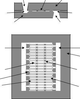
The first design of nanoporous membranes consisted of a bilayer of polysilicon with L-shaped pore paths. The flow path of fluids and particles through the membrane is shown in (Figure 15.2A) [20]. As shown, fluid enters the pores through openings in the top polysilicon layer, travel laterally through the pores, make a 90◦ turn, and exit the pores through the bottom of the pore where both the top and bottom polysilicon layers lay on the etch stop layer). While this design performed well for preventing the diffusion of the larger, unwanted immune system molecules, its L-shaped path slowed down and, in some cases, prevented the diffusion of the smaller molecules of interest. The pores in this design were fairly long, which led to the slow diffusion of the desired molecules. Also, because of the large area per pore, it was difficult to increase the pore density and thus the diffusion rate. The next design had an improvement in the production of short, straight, vertical pores through a single crystal base layer. This design had the advantage of direct flow paths (Figure 15.2B) [20]. This direct path allows the smaller molecules of interest to diffuse much quicker through the membrane, while still size-separating the larger molecules. To further improve the reliability of the nanoporous membranes, several basic changes were made in the fabrication protocol from the previous membrane design to eliminate problems with the diffused etch stop layer [43]. This design also incorporated a shorter diffusion path length, based on the thicknesses of the two structural layers. The design of a new membrane fabrication protocol

266 |
TEJAL A. DESAI ET AL. |
FIGURE 15.2. (A) Flow path through M1 filters, with lateral diffusion through the nanopores defined by sacrificial oxide. (B) Cross-section of M2 design showing dirext flow path. Scanning electron micrographs of microfabricated membrane: (C) top view detail; (D) side view detail.
incorporated several desired improvements: a well defined etch stop layer, precise control of pore dimensions, and a lower stress state in the membrane (Figure 15.2C & 15.2D). The new protocol also increased the exposed pore area of the membranes.
Most recently, we have developed nanochannel delivery systems (called nDS) with improved mechanical stability [62]. These devices are based on bulk micromachining and sandwich encapsulated filter design [68]. The nDS device consists of two bonded silicon wafers: the micromachined filtration structural wafer and the cap wafer (Figure 15.3). Fluids enter through the hole etched in the cap wafer, then flow horizontally through the filtration channel as defined by the gap between the cap wafer and the machined features on the structural wafer, and then out the hole etched in the structural wafer. Since the flow is between two directly bonded wafers, the filter has more mechanical support and is thus structurally stronger. Another advantage to the encapsulated-channel filter lies in the fabrication process: a bulk micromachined structure requires less complicated fabrication steps than a surface-micromachined one and thus leads to a simpler and faster process flow. The features on the structural wafer are shown in Figure 15.3 and are fabricated using bulk micromachining. To achieve high throughputs, interdigitated finger geometry was used. The first devce in our proposed sequence of delivery systems is the passive release device called nDS1. Future embodiments will have the capability of integration of electronics on board, and are being developed for preprogrammed- (electroosmoticaly driven, nDS2) and remote-activated (drug on demand, nDS3) delivery of drugs.
NANOPOROUS IMPLANTS FOR CONTROLLED DRUG DELIVERY |
267 |
|
Entry hole |
Channel Cap wafer |
|
A
Entry |
Exit flow |
|
flow |
||
chamber |
||
chamber |
||
|
||
Structural wafer |
Exit hole |
B
Entry |
Exit flow |
|
flow |
||
Chamber |
||
chamber |
||
Anchor |
||
|
||
|
region |
|
Channel |
Anchor |
|
point |
||
|
||
Spacer |
|
|
layer |
|
|
Input |
Output |
|
finger |
finger |
FIGURE 15.3. (A) Cross-sectional view of the nanochannel delivery system (nDS). (B) Top and cross-sectional view of nDS structure on the structural wafer.
15.1.3. Comparison of Nanopore Technology with Existing Drug Delivery Technologies
The nanopore delivery technology discussed here is based on the bulk and surface processing of single crystal silicon wafers, and thin layers of polysilicon, silicon oxide, and silicon nitride. It offers distinct advantages in the scaleability of the manufacture (obviously demonstrated by the world-changing successes of the microelectronics industry and, to a lesser extent, of micro-electro-mechanical-systems (MEMS)), exquisite device replicability, and the possible integration of complex electronic functionalities.
The most important competitor to our proposed technology is the IV administration of bioacive agents, which is associated with obvious difficulties in terms of patient inconvenience, discomfort, required hospital stay, and adverse affects such as phlebitis and infections. While it is impossible to review here in any detail the very broad field of drug-delivery technology, it is noted that development of drug delivery systems encompasses broad categories, such as implantable devices with percutaneous components, fully implantable devices, polymer-based systems, microchips, and osmotic pumps. Krulevitch and Wang [41] described a microfabricated, fully integrated drug delivery system capable of secreting controlled dosages of drugs over long periods of time, while Cao, Lai, and Lee [29] describe a self-regulated drug delivery device that integrates both mechanical and chemical methodologies. Numerous polymer systems have been employed [60, 74, 52] with varying degrees of success. Infection is a major concern
268 |
TEJAL A. DESAI ET AL. |
with clinically available implantable drug delivery pumps, as are catheter-related complications, such as kinking, dislodgements, disconnections, tears and occlusions [26]. Furthermore, catheter-tip inflammatory masses continue to be a problem with current devices [30]. Poor patient compliance is a significant obstacle that often leads to suboptimal treatment and inferior outcomes [4, 18, 25]. In fact, poor compliance is the most common cause of medication failure [6, 56]. For patients with terminal illness in particular, discouragement and lack of conviction regarding the effectiveness of treatments result in poor compliance [64]. These problems could potentially be ameliorated though the use of appropriate implantable drug delivery systems. Implants with degradable polymers suffer from two major drawbacks. Polymer depots exhibit an initial “burst effect” prior to sustained drug release, and typically are not as efficient in controlling release rates of small molecules [53]. The use of implantable devices with percutaneous components such as ambulatory peritoneal dialysis catheters, intravenous catheters and orthopedic implants, is complicated by such occurrences as infection, marsupialization, permigration, and avulsion [31, 32].
In spite of recent developments in the drug delivery technology, there is no clinically available device that has been shown to be able to perform the controlled, long-term diffusion of the agents on interest here. Potential alternative approaches that might be employed are A: Osmotic pumps [67]; and B: MicroChips developed by Santini, Cima, and Langer [57–59]. The former employs an osmotic piston to provide the zero-order release of drugs, and has been clinically demonstrated for the constant-rate administration of leuprolide in the management of prostate cancer [27, 74]. The device developed by Santini et al. employs the electrochemical dissolution of the cover of a number of reservoirs to obtain the controlled release of their contents. Ideally, this methodology may yield a desired, and potentially variable, release profile. Neither one of these two potentially alternative release devices have been proven capable of providing the zero-order release of the immunomodulating molecules of interest in the research protocol presented herein. Expected problems that might present themselves, were one to attempt the employ osmotic pumps or the MicroChip device by Santini et al. to perform the experimental protocols described in this proposal, include: concerns with formulation and mass transport dynamics, leading to expectedly high and potentially unsafe pressures in the ALZET chamber; and loss of functionality of the therapeutic moieties. Furthermore, it remains to be proven that the desired release profiles, especially for what concerns the variable rates, could be met with the MicroChips. The ALZET pump is, by its very design, incapable of performing variable rates, or arresting the release once it is started. A further disadvantage is the difficulty of developing an effective dosage solution to deliver lipophilic compounds [5, 40]. By contrast, the devices fabricated by our group are based on constrained diffusion and controllable electrokinetic transport, and therefore will not lead to any build up of pressure during its use. It will not require the development of novel formulations, since the release of functionally active molecules has been demonstrated [44]. Future embodiments will have the capabilities for preprogrammedand remote-activated delivery of drugs.
In this review we will mainly focus on the fabrication, release characteristics, and biocompatibility issues of a small subcutaneous nanoporous implant named NanoGATE incorporating a microfabricated silicon nanoporous membrane engineered to the exact size and requirements of the individual molecule. The NanoGATE device is anticipated to slowly
NANOPOROUS IMPLANTS FOR CONTROLLED DRUG DELIVERY |
269 |
release the encapsulated drug at an optimal rate to mimic a slow infusion, so that the patient will have therapeutic levels of the drug in his/her body for the entire course of therapy. The drug reservoir of the NanoGATE device will contain a highly concentrated form of the drug either as a dry powder or concentrated suspension to minimize the size of the device required to hold the cumulative dose required for an extended period of treatment (e.g., 3 to 6 months). At present NanoGATE technology is being developed to deliver Interferon- α for the treatment of chronic hepatitis C. Interferon α delivered through a NanoGATE subcutaneous implant is expected to provide significant medical advantages over the current treatment modalities.
15.2. FABRICATION OF NANOPOROUS MEMBRANES
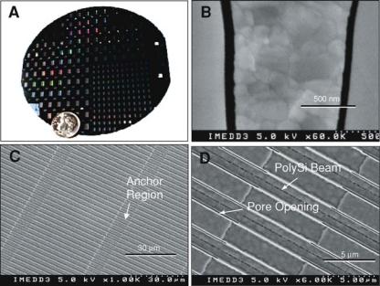
We have used top-down microfabrication methods to create nanopore membranes consisting of arrays of parallel rectangular channels which, in their smallest aspect, range from 7 nm to 50 nm (Figure 15.4). The original method pioneered by Ferrari and colleagues [12] consists of two basic steps: (1) Surface micromachining of nanochannels in a thin film on the top of a silicon wafer, and (2) Forming the nanopore membrane by etching away the
FIGURE 15.4. Photographic images of nanopore membranes. (A) Appearance of 4 in silicon wafer showing 120 small and 100 large membrane dies before being cut into individual units. (B) SEM cross-sectional view of membrane with 50 nm pores separated by silicon and poly-silicon material. (C) SEM top view of membrane with pores at 1000X magnification showing 45 μm long pores separated by 10 μm long anchor regions. (D) 6000X top SEM view of membrane showing details of pore and anchor structures.
270 |
TEJAL A. DESAI ET AL. |
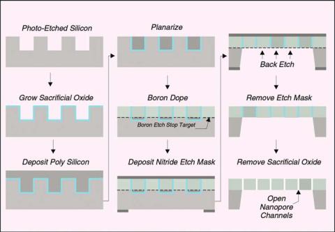
FIGURE 15.5. Schematic of key steps in silicon nanopore membrane fabrication process.
bulk of the silicon wafer underneath the thin-film structure. The overall fabrication process is shown schematically in Figure 15.5.
The first major process step involves etching channels in the silicon substrate over its entire surface to define the overall shape of the pores (Figure 15.5A). The etched channels are 2 μm wide separated by 2 μm and they are 5 μm deep. These channels are formed using a plasma-etch procedure with a thermally grown oxide layer as an etch-mask.
The next major step involves growing a sacrificial oxide-layer over the entire wafer surface including the surface area of the channels (Figure 15.5B). The sacrificial-oxide layer thickness defines the channel width in the final membrane. Proper selection of the time and temperature of this thermal oxidation step allows for control of the sacrificial layer thickness to tolerances of less than 0.5 nm across the entire wafer.
Anchor points are created within the channels to define the pore length (45 μm distance). These anchor points are 10 μm long and they are formed between each 45 μm -long pore region. The anchors provide rigidity to the membrane structure because there are no pores in the anchor regions. The anchor points are formed across the entire wafer by selectively etching through the sacrificial layer in a series of 10 μm-wide strips perpendicular to the channel direction.
The next fabrication step involves filling the channels using a polysilicon deposition process (Figure 15.5C). This filling step forms the membrane structure by providing silicon material on each side of the sacrificial oxide layers. The deposition also provides solid silicon—polysilicon areas in the anchor regions to stabilize the membrane. The deposited
NANOPOROUS IMPLANTS FOR CONTROLLED DRUG DELIVERY |
271 |
polysilicon layer is then “planarized” (see Figure 15.5D) using a plasma-etch process leaving a smooth surface structure with the pores exposed. An SEM photograph image of the planarized membrane surface is shown in Figure 15.1.
Following planarization, a boron-doping step is performed where boron ions are diffused into the surface of the silicon-polysilicon material to a depth of 3 μm (see dashed line in Figure 15.5E). Boron-doped silicon etches in KOH at a much lower rate than undoped silicon so the boron doping provides an etch-stop that will later define the membrane thickness.
A protective nitride mask layer is then deposited on the wafer completely covering both sides. This layer is impervious to the KOH chemical etch that will be used to form the membranes out of the silicon substrate. On the backside of the wafer, windows are plasmaetched in the nitride layer to define the membrane dimensions (i.e., a series of 1 × 2 mm windows for the small membrane dies and 2 × 3.5 mm windows for the large-membrane dies in Figure 15.4A). These windows in the protective nitride layer expose the silicon wafer to KOH etchant in the desired regions (Figure 15.5F).
The wafer is then placed in a 55◦C KOH bath to etch the unprotected silicon through the windows in the nitride and up to the boron etch-stop to form the membrane (Figure 15.5G). After the silicon is removed, the protective nitride etch mask (Figure 15.2H) and sacrificial oxide (Figure 15.2I) are removed using an HF etchant. This final etching step opens the pores and provides the desired nanopore membrane structure.
15.3. IMPLANT ASSEMBLY AND LOADING
All NanoGATE implant housing components were obtained from Manufacturing Technical Solutions (Carroll, OH). A 2 × 3 mm nanopore membrane die was affixed over a small-bore opening within a cylindrical methacrylate insert carrier fitted with two rubber O-rings using general purpose silicone adhesive and allowed to cure 3 h at 55◦C. The completed carrier was inserted into the titanium encasement until the nanopore membrane region was fully aligned under the grate opening. Methacrylate end caps containing resealable rubber septa were sealed at each end of the titanium encasement using silicone adhesive and allowed to cure. Figure 15.6 shows a drawing the NanoGATE implant fitted with nanopore membrane (top) and a photograph of prototype implant illustrating its size in relation to a US 1 cent piece (bottom). For filling, the implant was oriented vertically and a 27 gauge luer-lock needle was inserted into the upper septa for use as an air vent. The liquid suspension was slowly injected into the implant via the lower septa until all the air within the implant was removed, as indicated by the presence of liquid exuding from the upper needle. The needles were removed under gentle liquid injection pressure to avoid any concomitant influx of air upon withdrawal. The implants were rinsed by immersion in appropriate buffer prior to either placement into a testing vessel or surgical implantation.
15.4. NANOPOROUS IMPLANT DIFFUSION STUDIES
Fick’s laws are usually adequate to describe diffusion kinetics of solutes from a region of higher concentration to a region of lower concentration through a thin, semi-permeable

272 |
TEJAL A. DESAI ET AL. |
FIGURE 15.6. Implant device fitted with nanopore membrane. (Top) Drawing illustrating key features of the device. The dashed arrow represents a possible diffusion path of a drug molecule held within the device reservoir. (Bottom) Photograph of prototype implant device illustrating its size in relation to a US 1 cent piece.
membrane. As the size of the membrane pores approaches that of the solute, however, unexpected effects can occur, which deviate substantially from those predicted by Fick’s laws. Diffusion of molecules in microporous media such as zeolites has led to experimental evidence of such unusual phenomena as molecular traffic control and single file diffusion (SFD) (1-6) [16, 28, 29, 42, 51, 71]. Theoretical treatments and simulations suggest that in the case of SFD solute molecules of equal size cannot pass each other in pores which approximate the dimensions of the molecule itself, regardless of the influence of concentration gradient, and thus their initial rate of movement (or flux) is underestimated by Fick’s law [1, 2, 44, 48, 49, 54].
During development of the immunoisolating biocapsule, it was noted that diffusion through nanopore membranes, when using the smaller pore sizes, was slower than predicted from Fick’s law. To explore this phenomenon, the relationship between diffusion rates of various solutes and the width of nanopore membranes was investigated [50].
15.4.1. Interferon Release Data
The interferon release profile is shown in Figure 15.7, the membrane used in the experiment has 20 nm pore size, the initial concentration in the donor well is 4.68 mg/ml, and the Stokes Radius of interferon is about 2.3 nm. The solid line has been obtained by

NANOPOROUS IMPLANTS FOR CONTROLLED DRUG DELIVERY |
273 |
FIGURE 15.7. In vitro interferon diffusion through nanopore membrane (20 nm pore size): experimental data (◦), Fick’s law prediction (-), model based simulation (- -).
simply combining the first Fick’s law with the mass conservation principle, and multiplying the mass flux times the total nominal pores area: the resulting diffusion profile, as well known, results to be exponential. The steady state value is close to 100% of the amount of drug loaded into the donor well, because the acceptor well volume is much larger than the donor well, therefore, in order to make the concentration homogeneous on both sides of the membrane, only a little amount of drug has to be retained in the donor well.
Looking at the experimental measurements (circle markers), it is fairly clear that, even changing the parameters values with respect to the nominal ones, the experimental diffusion profile could not be explained by Fick’s law, because it is not exponential. On the contrary, the release rate keeps constant (zero order kinetics) for a long period (about 25 days), until 75% of the total amount has been released. Later on we will discuss how to interpret this result and to devise a suitable theoretical diffusion model fitting the data (dashed line).
15.4.2. Bovine Serum Albumin Release Data
Experiments, like the one described in the previous section, indicate that nanopore membranes can be engineered to control diffusion rates and kinetic order by “fine-tuning” channel width in relation to the size of solutes. Moreover, when the proper balance is struck, zero-order diffusion kinetics is possible. Implantable zero-order output devices are useful to deliver drugs which are not orally bioavailable, particularly in clinical settings where maintenance of a steady state level in the blood stream for long periods is desirable [74]. The nanopore membrane offers a non-mechanical means to achieve such release kinetics for delivering small molecular weight organic drugs as well as larger peptideand protein-based biopharmaceuticals.
274 |
TEJAL A. DESAI ET AL. |
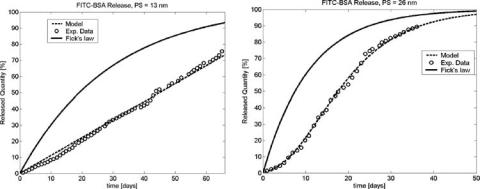
FIGURE 15.8. In vitro diffusion kinetics of fluorescein isothiocyanate (FITC) labeled-BSA through (A) 13 nm pore size and (B) 26 nm membrane under sink conditions: experimental data (◦), Fick’s law prediction (-), model based simulation (- -).
As a point of reference, the hydrodynamic diameter of a typical biopharmaceutical ranges between about 4 nm and 15 nm and a typical small organic drug may be 3 nm to 5 nm in size [33]. Thus, the widths of these nanopore channels can be made to approximate molecular dimensions. To test the system we selected bovine serum albumin (BSA, MW 66,000 Da, Stokes radius 3.88 nm) as a surrogate of a fairly large protein biopharmaceutical. Virtually no BSA diffusion is seen through nanopore membranes of 7 nm (data not shown), which would be expected since the hydrodynamic diameter of BSA is about 8 nm. In vitro release of fluorescent-labeled BSA loaded into implants fitted with nanopore membranes of two sizes, 13 nm and 26 nm, under sink conditions is shown in Figure 15.8. Fick’s expected behavior is depicted in the figure and compared with an interpolation, obtained from a dynamical diffusion model, which will be discussed later on.
The mass flux is constant in the 13 nm case (Figure 15.8A), and zero order kinetics is maintained for the whole experiment duration, while the 26 nm test data (Figure 15.8B) show an exponential release profile. Note that, in the latter case, there is a second order effect, which creates a kind of inertia in the initial days: the release rate starts from a very low value, then increases till the curve assumes a slope close to that predicted by Fick’s law. This phenomenon occurs in some experiments, and is caused by an unsuccessful pre-wetting of the pores, thus it has to be neglected on a par with experimental errors.
As one would intuitively expect, even with pore sizes greater than 26 nm, BSA diffusion remains Fickian (data not shown). These data indicate that flux can be controlled by porosity, and kinetic rate by channel width.
In order to capitalize on the constrained diffusion feature offered by these nanopore membranes, we tested their utility as a means of controlling the bioavailability of a protein in vivo. Devices fitted with 13 nm membranes and filled with 300 μl of a solution containing 0.15 mg of 125I-BSA were implanted subcutaneously in the backs of 3 rats. The devices were adjusted to have an in vitro output rate of 15 μg/day and thus were designed to release the albumin for about 100 days. The pharmacokinetics of the labeled BSA in blood was measured and compared to a dose of BSA delivered by a standard subcutaneous bolus injection. Figure 15.9 shows the mean values for blood levels over a period of 45 days