

Environmental Biotechnology - Jordening and Winter
.pdf12.2 Investigations 315
Fig. 12.3 Laboratory test methods for investigating and optimizing microbial degradation of contaminants (according to [1]).

316 12 In-situ Remediation
technical scale. Hence, it is necessary to use indirect parameters to demonstrate biodegradation.
Investigations of numerous sites have shown that the indigenous microflora often include specific contaminant degraders. Therefore, in principle, the degradation potential is given, unless the contamination reaches toxic concentrations. Environmental conditions are usually unfavorable for rapid degradation. In the first stage of investigation the maximum degradation rate is determined, instead of a realistic rate.
During the second stage, basic data for planning the remediation, such as nutrient demand, remediation duration, and achievable end concentrations, are determined by test methods that simulate the remediation technology (benchtop scale).
The results of all site investigations and of risk assessments are considered when planning the remediation. Today, sufficient experience is available to scale up the results of bench-top scale investigations to a technical scale. Pilot scale investigations are carried out when new technologies without sufficient practical experience are being considered, recalcitrant contaminants need to be treated, or the site exhibits special complex conditions.
The data collected for a specific site are used to describe the site (conceptual site model). From this site model, laboratory investigations are designed. The laboratory results are used to plan the technical scale remediation. For in situ remediation, it is reasonable to use an additional planning instrument – modeling. These models are fed with parameters determined during site and laboratory investigations.
12.3
Remediation Technologies
12.3.1
General Considerations
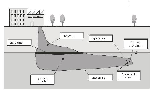
Figure 12.4 shows the typical characteristics of long-term pollution. Contaminants enter the soil and migrate downwards. The amount of contaminants remaining in the unsaturated zone is controlled by sorption, diffusion into soil pores, and retention by capillary forces. Generally, most contaminants have low solubility; hence, high amounts of contaminants may appear – when they reach the groundwater table. Depending on their buoyant density, a separate phase on top of the groundwater, called LNAPL (light nonaqueous-phase liquid), or at the base of the aquifer (groundwater zone), called DNAPL (dense nonaqueous-phase liquid) may occur. Minor amounts of contaminants are dissolved in the groundwater and are transported with the natural groundwater flow, forming a contaminant plume. The spatial extent of the plume and the contaminant concentrations depend on the duration of the pollution, the sorption and transport characteristics, and the efficiency of the natural biotic and abiotic degradation processes.
Depending on the characteristics of the contaminants and on the site conditions, different technologies have to be chosen. The technologies are divided into technol-
12.3 Remediation Technologies 317
Fig. 12.4 Localization of different microbial in situ technologies.
ogies for treatment of the unsaturated and saturated soils. A further subdivision comprises active and passive technologies. All these technologies can be combined with bioaugmentation, which is the addition (i.e., infiltration) of specific contami- nant-degrading bacteria previously isolated and propagated in the laboratory. However, bioaugmentation is still controversial, because the majority of the infiltrated cells become attached to the soil within a few centimeters. Furthermore, establishing added microflora in an environmental compartment requires highly specific conditions [2]. Usually, the infiltration of nutrients during the remediation causes the added bacteria to be overgrown by the autochthonous microflora. Most technologies include not only degradation of the contaminants in situ but also physical removal of the contaminants (e.g., together with exhausted soil vapor or pumped groundwater), which requires an additional treatment step.
12.3.2
Treatment of Unsaturated Soil (Bioventing)
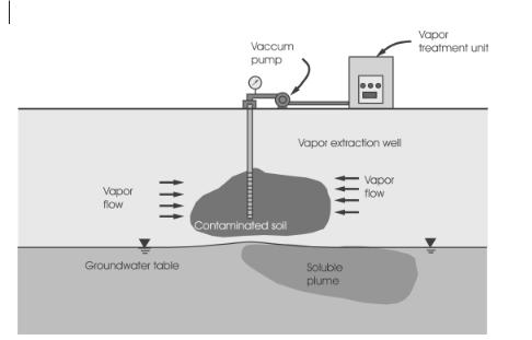
The only biotechnological in situ technology available for treating unsaturated soil is bioventing. The process scheme is shown in Figure 12.5 [3] and is based on vacuumenhanced soil vapor extraction. The pressure difference in the subsurface causes an inflow of atmospheric air and therefore an oxygen supply, as needed for aerobic contaminant degradation. Depending on site conditions, nutrients may need to be added, e.g., by sprinkling nutrient solutions on top of the soil or by installing horizontal infiltration drainage above the contaminant soil zone.
318 12 In-situ Remediation
Fig. 12.5 Process scheme of bioventing.
One of the most important tasks of process design is to ensure a sufficient air flow regime within the soil. In particular, the geometry of the exfiltration wells, the necessity of active or passive air injection wells, and the need for ground sealing need to be considered. High contaminant concentrations may clog the soil pores, leading to reduced efficiency of oxygen supply. If this occurs, a pulsed soil vapor extraction method may be of advantage.
If the contaminants to be treated are volatile, the extracted soil vapor has to be treated, e.g., by sorption of the contaminants on activated carbon or by biodegradation within a biofilter. Bioventing is applicable to treating petroleum hydrocarbons, aromatic hydrocarbons, and other comparable contaminants. Because soil vapor extraction dries the soil, the water budget of the soil can be adjusted with the nutrient addition. Optimum biodegradation requires a water content of 40%–60% of the maximum water holding capacity. A lower water content reduces the biodegradation rates, a higher water content leads to water-saturated zones in which air flow is not possible and aerobic biodegradation is prevented.
Bioventing is easy to monitor (Section 12.4). Under optimal conditions degradation rates of about 0.2–20 mg kg–1 d–1 for petroleum products in soils of medium permeability can be achieved. The degradation rates in the processes for the treatment of the saturated soil are influenced by many more parameters; hence; these rates diverge to a much higher extent.

12.3 Remediation Technologies 319
12.3.3
Treatment of Saturated Soil
12.3.3.1Hydraulic Circuits
Hydraulic circuits comprise groundwater pumping, cleaning, addition of nutrients, and reinfiltration. The contaminants are degraded in the subsurface (in situ) or are removed with the groundwater and eliminated in the groundwater treatment plant. This technology is the first to be applied in situ and thus is the most understood. The technique has mainly been used to treat mineral oil contamination. Mineral oil hydrocarbons (MHC) are extractable to only a very small extent. During complete remediation less than 1% of the MHC can be removed with the exfiltrated groundwater; the rest has to be biodegraded in situ. However, monoaromatic hydrocarbons, a cocontaminant of mineral oil products, can be washed out to a greater extent. The rate of in situ degradation and exfiltration depends on the solubility of the contaminants, the kinetics of biodegradation, and the process technology. Because pumping and treatment of groundwater are expensive, the process may be designed to minimize the amount of groundwater to be pumped. Both the process and the complete in situ infrastructure, including the positioning and size of pumps and infiltration wells, can be chosen on the basis of process modeling.
Below, a specific hydraulic circuit design is described. At the site a gravel filter (0.5 m) was installed at the level of the groundwater table after and before refilling of the excavation on-site treated of unsaturated soil. The gravel filles contained drainage pipes that collected and transported the groundwater to the pumping wells. The pumped groundwater was sent to a water treatment plant, where Fe, Mn (to prevent clogging of the plant by hydroxides), and the contaminants were removed. The cleaned water was supplemented with nutrients (urea, phosphoric acid) and the electron acceptors hydrogen peroxide (H2O2) and nitrate (NO3–). The supplemented water was infiltrated at the bottom of the aquifer and pumped from the groundwater table. The resulting vertical groundwater flow direction improved uniform distribution of the nutrients. The locations of the pumping wells have to be chosen in so that no contaminants can escape from the site along with the natural groundwater flow. This may also be achieved by enclosing the site within a slurry wall reaching down to the aquiclude (groundwater-impermeable layer).
12.3.3.2Special Groundwater Wells
A variety of special groundwater wells have been developed, which have two common features. They cause groundwater circulation and stripping within the well, resulting in an intensive throughput of groundwater and, therefore, an efficient supply of nutrients and electron acceptors (air oxygen or others, e.g., H2O2). Furthermore, volatile compounds are stripped within the well. The waste air is extracted and cleaned on-site.
The individual techniques are called groundwater circulation wells, in-well stripping, and BioAirliftT. The wells consist of a combined system of groundwater removal and infiltration within the wells. To allow circulation of groundwater the well

320 12 In-situ Remediation
is screened at the bottom and at the groundwater table. Both areas are separated by a cover pipe and bentonite sealing. A pipe is used to inject atmospheric air at the bottom of the well. This causes upstreaming of the water according to the principle of a mammoth pump and simultaneously a stripping of volatile compounds. The elevation of the water table within the well leads to infiltration of the oxygen-enriched groundwater at the top of the groundwater level. After circulating within the aquifer, the water enters the well again at the bottom.
Additional elements can include nutrient infiltration pipes within the well. An electric water pump may be installed instead of the mammoth pump. If so, no stripping and no oxygen enrichment of the groundwater occur. An electric pump may also be installed in addition to a mammoth pump. Furthermore, a permeable bioreactor containing immobilized contaminant-degrading bacteria can be installed between the points of water input and output. However, the water flow velocity is usually too high to allow significant degradation of the contaminants within the residence time in the bioreactor. Therefore, the reactor material also contains activated carbon. The contaminants are sorbed onto the carbon, which is reactivated by biodegradation of the contaminants within the reactor. The reactor may also contain other materials such as an ion exchanger (to remove heavy metals) or only activated carbon, if the contaminants are not sufficiently biodegradable (e.g., PAH).
If there is additional contamination of the unsaturated soil, the outlet of the groundwater may be installed above the groundwater table. With this type of operation the unsaturated zone (at least the groundwater fluctuation zone) can be flushed with nutrient-enriched water. Alternatively, the well can be combined with a vaporextraction system. Here, bioventing of the unsaturated soil may also be induced. These special wells have been used to remediate sites polluted with petroleum hydrocarbons, aromatic hydrocarbons, or volatile chlorinated hydrocarbons.
12.3.3.3 Biosparging and Bioslurping
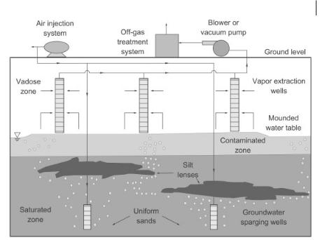
Both biosparging and bioslurping are not restricted to treatment of the saturated zone, but are also used for treatment of the unsaturated zone. Biosparging is the injection of atmospheric air into the aquifer (Fig. 12.6) [4, 5], which results in the formation of small branched channels through which air moves to the unsaturated zone. Outside these channels all processes are limited by diffusion. Therefore, highly branched channels are desired, which can be achieved by pulsing the air injection. Biosparging enhances the in situ stripping of volatile contaminants, desorption of contaminants, and their degradation by enriching the groundwater with oxygen. Because the contaminants are transported to the unsaturated zone, biosparging is usually combined with soil vapor extraction. Biosparging is applicable if the sparging point can be installed below the zone of contamination, because air flows upward, forming a cone. The angle of the cone and the degree of branching of the channels in a given soil depend mainly on the injection pressure, which should be only a little higher than the pressure of the water column. Usually the radius of influence of a biosparging well is determined by a pilot test at the site. At various distances from the sparging point, additional wells are installed to monitor groundwater level and
12.3 Remediation Technologies 321
Fig. 12.6 Process scheme of biosparging.
oxygen saturation. An increase of the groundwater table is observed only in the beginning of the treatment, and after the air channels are formed the groundwater returns to its original level. Biosparging is very sensitive to soil inhomogeneities. Zones of lower permeability may deflect the air channels. Zones of high permeability may act like open pipes channeling the air flow. In both cases the soil above these zones remains untreated. Additional nutrients to enhance microbiological degradation may be infiltrated with the same biosparging wells or with separate infiltration wells.
Bioslurping (also known as vacuum-enhanced recovery) is the only technology that also treats free product phases floating on top of the groundwater [3, 6]. Bioslurping wells (gas-tight at the well head) are mainly screened within the groundwater fluctuation zone. A suction pipe is directed within the free phase. By applying a vacuum, a mixture of free product, soil vapor, and groundwater is extracted. Above ground all three media (free product, waste air, and water) are separated. Free product is collected, and water and waste air are cleaned separately. The treatment plant can be small and run at comparatively low cost because only a small amount of groundwater and soil air is extracted. The main advantage of bioslurping is the horizontal flow of the free product. Compared to conventional recovery systems, e.g., by hydraulic gradients toward a pumping well, bioslurping does not enhance the smearing of the free phase to greater depths of the aquifer. The accompanying extraction of soil vapor leads to enrichment of the soil with oxygen, comparable to bioventing. Hence biodegradation in this zone is enhanced. Bioslurping can be com-
322 12 In-situ Remediation
bined with infiltration of nutrient salts into the vadose zone or into the saturated zone.
12.3.3.4 Passive Technologies
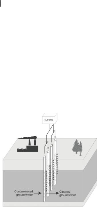
Experience shows that all active technologies require homogenous geological conditions. If these conditions do not pertain, passive technologies may be of advantage. Furthermore, the low solubility of hydrophobic organic contaminants and the slow diffusion of contaminants that have been within soil micropores for decades may result in a low efficiency of remediation technologies based on induced groundwater flow. Passive technologies are used at or near the end of the contaminant plume. They consist of constructed zones (reactors) in which the contaminants are degraded. If the zones cover the complete cross section of the plume, the technologies are called activated zone, bioscreen, reactive wall, or reactive trench. The main difference between these techniques is the need for soil excavation. Whereas activated zones or bioscreens are arranged without any soil management, the reactive wall and reactive trench techniques require construction of a subsurface bioreactor. Activated zones can be arranged, for example, as a line of narrow wells perpendicular to the direction of groundwater flow (Fig. 12.7). Incompletely passive technologies comprise alternating pumping and reinfiltration of groundwater in closed, directly linked loops, combined with an in-line nutrient amendment system consisting of a
Fig. 12.7 Process scheme of activated zones.

12.3 Remediation Technologies 323
water-driven proportional feeder and a reservoir [7]. In this system the autochthonous microbial population is stimulated to adapt to a new and suitable redox situation and to develop the appropriate contaminant-degrading activity [8]. In such systems the hydraulic conductivity of the activated zone is the same as in the surrounding aquifer. Any alteration, e.g., by iron hydroxide precipitation, may lead to a reduction of hydraulic conductivity and a changed groundwater flow regime, which may result in deficient contaminant treatment.
Completely passive systems were developed because such exfiltration–infiltration loops consume significant amounts of energy. The advantage of passive systems is the highest when the energy demand is the lowest. This is true of completely passive systems, in which the remediation time is long and the contaminant load to be treated is usually low. In these completely passive systems, the wells are, for example, charged with solid cylinders consisting of highly permeable structural material (sand/cement) and so-called oxygen-release compounds (ORC®), which represent a proprietary MgO2 formulation. This compound releases oxygen over a period of about 300 d. If the ORC is exhausted. the cylinders can be easily replaced with fresh ones.
Because degradation of numerous contaminants requires anaerobic conditions, it is necessary to supply electron donors (e.g., hydrogen) in completely passive systems. Hence, hydrogen-release compounds (HRC®) were developed. This product is used especially to enhance the in situ transformation of volatile highly chlorinated hydrocarbons. These viscous compounds must be supplied via high-pressure injections.
At present, many different substances are used for injection into the groundwater to construct so-called in situ reactive zones (IRZ), including H2O2 for aerobic biodegradation and molasses, whey, or chitin for anaerobic biodegradation. Current investigations are concerned with the electrochemical generation of hydrogen as electron donor (2 H2O → O2 + 2 H2). The cathode where H2 is generated can be located within an anaerobic treatment zone, but the anode where O2 is generated is located within an aerobic treatment zone.
Reactive walls or comparable systems are local zones in a natural porous medium exhibiting high contaminant retention capacity and increased bioactivity. For reactive walls, systems with high longevity and without significant maintenance or the necessity of nutrient replenishment are desirable. Reactive walls can be composed of a mixture of organic waste (compost, wood chips, sewage sludge, etc.) and of, e.g., limestone for pH correction. The organic waste serves as a nutrient source, a structural material to establish high permeability, and a source of bacteria. A carrier (e.g., activated carbon) coated with specific contaminant-degrading microorganisms can also be used. Reactive walls can be in place for the complete duration of the treatment. If so, the necessary amount of nutrients is calculated on the basis of mass balance. However, it is difficult to estimate the fraction of nutrient mass that will be available for contaminant removal. Alternatively, reactive walls can be constructed so that the wall material is exchangeable or restorable. The materials have to be homogenized prior to installation to avoid channeling within the wall. Online monitoring of wall permeability is necessary to avoid changes in the predicted groundwater

324 12 In-situ Remediation
flow regime. The thickness of the wall depends on the groundwater flow velocity within the wall, contaminant concentration, degradation rates, and the required concentrations at the downgradient side of the reactive wall. Long-time changes in the values of these parameters have to be considered. The use of a numeric groundwater flow model for designing the wall is helpful. At present, several types of reactive walls have been developed; however, experience on a technical scale is limited. Reactive walls are implemented as denitrification zones [9] or metal barriers with bioprecipitation [10] (see Section 12.3.3.6). An adverse effect during metal precipitation is high concentrations of Fe(II) and Mn(II), because they consume most of the precipitation capacity. Furthermore, because the metals stay within the reactive wall, mainly as metal sulfides, the permeability of the wall may decrease with time. If environmental conditions will not change and the long-time stability of the insoluble metal sulfides is known, they may remain in the subsurface; otherwise, the wall material has to be removed.
In general, reactive walls can be used with all biochemical processes that eliminate pollutants. However, site-specific conditions always need to be considered to show which technology is feasible and also economical.
Funnel-and-Gate™ is a system that channels contaminated groundwater, usually at the front of a plume, by means of impermeable walls (the funnel) toward gates within the wall, where a reactor is located (Fig. 12.8). To design such systems, use of a groundwater model that also considers inhomogeneities of the subsurface is essential. Within the gates, the same bioprocesses may be installed as in reactive walls. However, the smaller width of the bioreactors is favorable, because constructive measures to exchange the reactor material (e.g. reactor material filled cassette) are easier to implement. However, the groundwater flow velocity is increased within the gates and the groundwater table may rise. Full scale experience with Funnel-and- Gate technology is still rare in Europe. In particular, the longevity can be calculated only by extrapolation of short-term monitored processes. The advantage of these passive systems is low operation costs over long periods, since only monitoring is necessary.
12.3.3.5 Natural Attenuation
Contaminant transport in the groundwater results in dilution of the contaminants. In a certain distance from the contaminant source, concentration ranges can be reached in which available nutrients and electron acceptors are sufficient to allow complete degradation of the residual contaminants, resulting in a steady state of contaminant spreading and degradation or even in shrinkage of the plume if the source is removed or exhausted. The use of this site feature as ‘remediation’ is possible only if the extent of the plume in time and space can be forecasted reliably. Furthermore, it is necessary that sensitive receptors (targets) are not affected.
An essential part of natural attenuation is detailed knowledge of the hydrogeology and the use of reactive groundwater modeling. The geological and hydrogeological parameters of the model (e.g., sorption coefficients, hydraulic conductivity, ground-