

Environmental Biotechnology - Jordening and Winter
.pdf

410 17 Process Engineering of Biological Waste Gas Purification
in this liquid phase and are involved in removing the compounds acquired from the air. The microorganisms responsible for the biodegradation usually grow as a mixture of organisms. Such a mixture of different bacteria, fungi and protozoa depends on a number of interactions and is often referred to as a microbial community. Microorganisms are generally organized in thin layers called biofilms. The pollutants in the air (such as toluene, methane, dichloromethane, ethanol, carboxylic acids, esters, aldehydes, etc.; Tolvanen et al., 1998) usually act as a source of carbon and energy for growth and maintenance of the microorganisms. Some waste gases, such as those produced during composting, are composed of many (often up to several hundred) different chemicals, such as alcohols, carbonyl compounds, terpenes, esters, organosulfur compounds, ethers, ammonia, hydrogen sulfide, etc. (Tolvanen et al., 1998; Smet et al., 1999). The remarkable aspect of the microbial community is that it generally develops to a composition so that all these different chemicals are removed and metabolized simultaneously. Microorganisms also require essential nutrients and growth factors to function and produce new cells. These include nitrogen, phosphorous, sulfur, vitamins and trace elements. Most often these nutrients and growth factors are not present in the waste gas and have to be supplied externally.
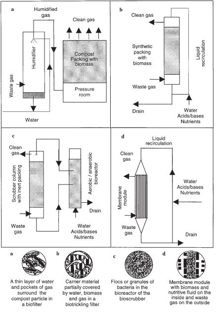
There are fundamental differences between the four types of reactors mentioned above. They range from whether the microorganisms are immobilized or dispersed to the state of the aqueous phase in the reactor (mobile or stationary). The aqueous phase significantly influences the mass transfer characteristics of the system. A short description of each of the four types of bioreactors for biological waste gas purification currently in use is given below (also see Figure 17.1).
17.2.2
Technology Types
17.2.2.1 Biofilter
In a biofilter, the air is passed through a bed packed with organic carrier materials, e.g., compost, soil or wood bark. The compounds in the air are transferred to a biofilm that grows on the filter materials. The nutrients necessary for growth of the microorganisms are supplied by the organic matter. On top of the biofilm is a thin liquid layer. An important control parameter is the moisture content of the overall carrier matrix, which must be between 40% and 60% (w/w). To avoid dehydration, the air is generally humidified before entering the biofilter. If the waste gas contains high levels of solid particles (i.e., the waste gas is an aerosol), an aerosol removal filter can be installed before the humidification chamber. This prevents clogging of the biofilter by the particles.
17.2.2.2 Biotrickling Filter
A biotrickling filter is similar to a biofilter. Here, pollutants are also transferred from the gas phase to a biofilm that grows on a packing material. However, the packing materials are made of chemically inert materials, such as plastic rings. Because nu-


17.3 Performance Parameters 413
17.3.1
Empty Bed Contact Time or True Contact Time
The residence time of the gas in a bioreactor can be calculated in two different ways;
•Superficial residence time or empty bed residence time, based on the total volume of the reactor and referred to as empty bed contact time (EBCT):
|
V 3600 |
|
EBCT = |
|
(1) |
|
||
|
Q |
|
where V = volume of filter material in the reactor (m3), and Q = waste gas flow rate (m3 h–1).
•True residence time ô, which is based on the free space in the reactor and defined as
ô = |
åV 3600 |
(2) |
Q
where å = porosity of the packing materials (dimensionless).
Often the exact porosity needed to calculate the true residence time is not known. Hence, most often the empty bed contact time is used. The EBCT is typically used for comparison of gas residence times in different reactor technologies or under different loading conditions. However, one has to remember that this gives an overestimation of the true residence time. Due to preferential currents through the larger voids in the packing, the actual residence time can differ considerably from the calculated residence time.
The residence time in the reactor is useful as an indicator of the time available for mass transfer of the pollutant from the gas phase to the liquid phase through the biofilm, which is often the factor limiting microbial degradation.
17.3.2
Surface Loading Rate (B A)
The surface loading rate indicates the amount of air that is passed through the bioreactor per unit surface area per unit time:
BA = |
Q |
(3) |
|
|
|||
A. |
|||
|
|
where A = total surface area of the packing or filter material in the bioreactor (m2). One can also express the velocity of the gas (m h–1) through the empty reactor.
However, the reactor is normally filled with packing materials, which results in a velocity of gas higher than the surface loading rate.

41417 Process Engineering of Biological Waste Gas Purification
17.3.3
Mass Loading Rate (B V)
The mass loading rate gives the amount of pollutant that is introduced into the bioreactor per unit volume and per unit time:
BV = |
QCg–in |
(4) |
|
V. |
|||
|
|
where Cg–in = concentration of the pollutant in the inlet waste gas stream (g m–3).
17.3.4
Volumetric Loading Rate (vS)
The volumetric loading rate is the amount of waste gas passed through the reactor per unit reactor volume:
|
Q |
|
vS = |
|
(5) |
|
||
|
V. |
|
17.3.5
Elimination Capacity (EC)
The elimination capacity EC gives the amount of pollutant removed per volume bioreactor per unit time. The overall elimination capacity is defined by Eq. (6):
|
Q (Cg–in – Cg–out) |
|
EC = |
|
(6) |
|
||
|
V. |
|
where Cg–out = concentration of the pollutant in the effluent waste gas (g m–3).
17.3.6
Removal Efficiency (RE)
Removal efficiency is the fraction of the pollutant removed in the bioreactor expressed as a percentage. It is defined as
RE = |
(Cg–in – Cg–out) |
(7) |
100 |
Cg–in
We should note that the various parameters are interdependent. There are only four independent design parameters: reactor height, volumetric loading rate, and gas phase concentrations at the inlet (Cg–in) and outlet (Cg–out).

17.4 Characteristics of the Waste Gas Stream 415
17.4
Characteristics of the Waste Gas Stream
Several characteristics of the waste gas stream have to be known when considering the implementation of biological waste gas purification technologies. Table 17.1 lists the characteristics of the waste gas stream that are essential for correctly designing a biological purification system.
Physical parameters such as relative humidity and temperature are important, because they have considerable influence on microbial degradation of the pollutant. Different microorganisms have different optimal ranges of temperature and relative humidity for growth. Temperature also affects the partitioning of the pollutant between the gas and liquid phases. The waste gas flow rate influences the volumetric loading rate of pollutant on the biologically active phase and, hence, the elimination capacity. Equally important are the identity and concentration of the pollutant and/or odor units in the waste gas stream, because they influence the overall efficiency of the biological waste gas system.
It is also important to establish the chemical composition of the waste gas stream before starting to design the treatment system. The microbial degradability of the pollutant in the waste gas stream is largely dependent on its chemical identity. The pollutant can be organic or inorganic. Typical organic pollutants that are often encountered in waste gas streams are ethers, ketones, fatty acids, alcohols, hydrocarbons, amines, and organosulfur compounds. Valuable information about the biodegradability of chemicals can be obtained, e.g., from Van Agteren et al. (1998). Waste gases can also contain inorganic compounds such as NH3, NO2, NO, H2S, and SO2. Some of these compounds may be present at toxic levels or they may reduce the degradation capacity by, e.g., acidifying the biofilter material. Therefore, either these compounds have to be eliminated before the waste gas stream enters the bioreactor, or a means of controlling the pH has to be installed. Different compounds can also
Table 17.1 Important characteristics of a waste gas stream.
Parameter |
Unit |
|
|
Relative humidity |
% |
Temperature |
°C |
Waste gas flow rate |
m3 h–1 |
Pollutant identity (chemistry) |
|
Pollutant concentration |
g m–3 |
Odor concentration |
ou m–3 |
Odor unit (ou) is the amount of (a mixture of) odorous compounds present in 1 m3 of odorless gas (under standard conditions) at the panel threshold (CEN, 1998).

416 17 Process Engineering of Biological Waste Gas Purification
affect each other’s degradation without being toxic to the microorganisms. Smet et al. (1997) reported that isobutyraldehyde (IB) had to be removed by a first layer of the biofilter before a Hypohomicrobium-based microbial community in a subsequent layer could develop and metabolize the dimethyl sulfide (DMS) present in the waste gas. In separate batch experiments they showed that the same Hypohomicrobium sp. switched its metabolism from using IB to consuming DMS when the IB concentrations decreased.
When bioreactors are used for odor abatement, the concentration of odiferous compounds in the waste gas has to be determined as well. The odor concentration in odor units per cubic meter (ou m–3) corresponds to the number of times a waste gas sample has to be diluted with reference air before the odor of the diluted sample can be distinguished from the reference air by 50% of the members of a standard panel. In this respect, the European Committee for Standardisation (CEN) is currently involved in standardizing the determination of odor compounds by dynamic olfactometry. This will improve the reproducibility of olfactometric measurements, basically by using panels standardized with respect to 1-butanol (detection threshold of 40 ppbv) (CEN, 1998). Although the evaluation of bioreactor performance aimed at odor reduction has to be based on olfactometric measurements, design and optimization always require chemical characterization of the overall process.
The concentration of the pollutants and/or odor units largely depends on the source of the waste gas stream. Waste gas streams from, e.g., hexane oil extraction processes have a pollutant concentration in the range of a few g m–3. On the other hand, for waste gas streams polluted with offensive odors, concentrations of the odorous compounds can be in the range of mg m–3 or less (Smet et al., 1998).
The characteristics of the waste gas stream determine to a large extent the type of bioreactor system that can be used. Table 17.2 gives a first indication of the suitability of bioreactors for waste gas purification in relation to the characteristics of the waste gas stream. Note the preponderant importance of the Henry coefficient. Chemicals that dissolve easily in water (hydrophilic substances) can be retained efficiently by scrubbing with water. Chemicals that are poorly water soluble (high Henry coefficient) are better dealt with by means of a biofilter. In Table 17.2, the mem-
Table 17.2 Pollutant concentrations, Henry coefficients, and concomitant operating parameters of biofilters, biotrickling filters, and bioscrubbers (after van Groenestijn and Hesselink, 1993).
|
Biofilter |
Biotrickling Filter |
Bioscrubber |
|
|
|
|
Pollutant concentration (g m–3) |
<1 |
<0.5 |
<5 |
Henry coefficient (dimensionless) |
<10 |
<1 |
<0.01 |
Surface loading rate (m3 m–3 h–1) |
50–200 |
100–1000 |
100–1000 |
Mass loading rate (g m–3 h–1) |
10–160 |
<500 |
<500 |
Empty bed contact time (s) |
15– 60 |
30–60 |
30– 60 |
Volumetric loading rate (m3 m–3 h–1) |
100–200 |
|
250–580 |
Elimination capacity (g m–3 h–1) |
10–160 |
|
|
Removal efficiency (%) |
95– 99 |
|
85– 95 |
|
|
|
|
17.5 Process Principles 417
brane reactor is not mentioned – depending on the nature of the membranes, it can be suited to handle a range of compounds (Stern, 1994).
17.5
Process Principles
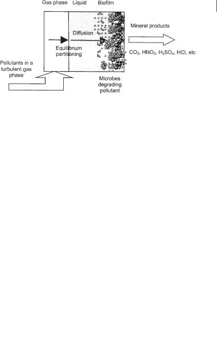
Several processes take place in biological waste gas cleaning systems. They include partitioning of the pollutant from the gaseous to the liquid phase, followed by its diffusion from the bulk liquid to the biofilm. Microbial degradation of the pollutant takes place in the biofilm, and the end products diffuse back into the bulk liquid. Mass transfer is the combined migration of compounds from the gaseous to the liquid phase and from the bulk liquid to the biofilm (Fig. 17.2).
17.5.1
Equilibrium Partitioning of the Pollutant
The first step toward microbial degradation of the pollutant is partitioning of the gaseous pollutants to the liquid phase. In a bioscrubber and biotrickling filter this is obvious, but also in a biofilter a small water layer is normally present on top of the microbial biofilm.
In describing gas–liquid mass transfer, the interfacial resistance between the liquid and the gas is often neglected. For practical reasons, it is usually assumed that straightforward partitioning of the pollutant between the two phases occurs, and the resulting concentration in both the gas and the liquid phase is at equilibrium. Equilibrium partitioning largely depends on the Henry constant of the pollutant.
The concentrations of the pollutant in the gas and liquid phases are related by Eq.
(8) (Sander, 1999).
Fig. 17.2 Schematic view of the sequence of processes leading to microbial degradation of pollutants in a biofilter.