Environmental Biotechnology - Jordening and Winter
.pdf
18.1 Background 429
filters may reach steady state through the establishment of a culture of predatory microbes that consume the decomposers, but again, heavy contaminant loads can cause rapid growth and pore clogging. Research on means to control or remove biomass remains active.
Water is readily available in biotrickling filters, but biofilters must be provided with humidification or irrigation systems to maintain the water content of the biofilm. All the systems require a source of nutrients such as nitrates and phosphates.
Each biological system must have an initial seed culture of microorganisms. Most often, a diverse mixed culture comes with the medium or is applied separately. It is presumed that those species capable of degrading the contaminant will grow rapidly, dominate the system, and create a dense culture ideal for efficient treatment.
A major design characteristic of a biological treatment system is the detention time. This is the average time that a parcel of air is held in the system. For a given flow, the minimum detention time determines the size of the reactor and so is a prime factor in determining the costs of the system. Because true porosity is often hard to measure, empty bed residence time (EBRT), calculated using the total volume of the bed, is often used to describe systems.
18.1.3
Biofilters
Biofilters are the most common form of biological air treatment system. The earliest and simplest were made by digging trenches, installing perforated pipe to serve as an air distribution system, and refilling the trenches with permeable soil. The Bohn Biofilter Corporation has installed many successful biofilters that are only slightly more complex, consisting of soil placed over a distribution system and contained within concrete traffic barriers (Bohn and Bohn, 1998). Soil biofilters are inexpensive. Soil is cheap and the construction methods are simple. Soil does not decompose significantly and so does not compact. It is easily rewetted if it is inadvertently allowed to dry. However, the pores are small, so that head losses are high when flow rates are high, and high contaminant loads cause clogging. These problems are avoided by making soil biofilters large, typically with detention times of a few minutes.
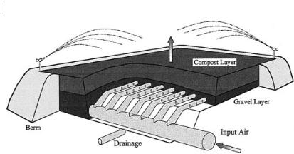
More complex biofilters are a pit or box filled with sieved compost or wood chips (Fig. 18.2). Once again, air is introduced through a distribution system at the bottom, typically perforated plastic pipes embedded in a layer of gravel or a layer of perforated concrete blocks. The compost or wood chips are placed above this, commonly in a layer about 1 m thick. A sprinkler system is provided to keep the medium moist, and drainage is provided to remove collected water in the event of rain or overwatering. Although these biofilters are somewhat more elaborate than soil biofilters, they can still be made cheaply. Because the particle size can be controlled, the organic media provide large pores to reduce head loss. They also provide nutrients as they slowly decompose. The diverse and active culture of microorganisms on compost allows it to start working immediately. The reduced head loss and ideal microbial environment mean that biofilters can be made smaller.
430 18 Commercial Applications of Biological Waste Gas Purification
Fig. 18.2 Schematic of an open bed compost biofilter.
Compost does have disadvantages, however. As it decomposes, small particles are generated, and the material softens and compacts. Compaction along the vertical axis tends to close the pores, increasing head loss. Horizontal shrinkage creates fissures in the medium and pulls it away from the walls of the vessel. Air is diverted from flowing through the medium to flowing through open channels, and treatment fails.
Compost also shrinks if it dries. Ideally, humidification and irrigation systems should prevent drying, but these occasionally fail. Once the compost has dried, it may become hydrophobic, making rewetting difficult.
The need to keep biofilters moist is a significant design consideration. Large amounts of air are passed through biofilters, so that air with a relative humidity even slightly lower than saturation causes a slow but steady drying that eventually disrupts operation. Relative humidity is a function of air temperature, and even modest warming also causes drying (Van Lith et al., 1997). Such warming can occur because of the pressure increase caused by a blower or because of heat generated in the biofilter by microbial oxidation of contaminants. To prevent problems, incoming air is often passed through a humidifier, typically a packed trickling bed. However, any warming of the air that occurs downstream (which always occurs for metabolic warming) again can reduce the relative humidity.
The water content of the porous medium can also be supplemented by direct irrigation, usually through sprinkling the top of the bed. This provides direct control, but it is sometimes difficult to ensure homogeneity. It is surprisingly difficult to arrange sprinklers to water uniformly, and partial clogging of the sprinkler nozzles commonly disrupts the distribution. Fine mist generators are better, because the mist droplets move with the air. Even when water is sprinkled uniformly on the surface of the bed, downward flow tends to ‘finger’, concentrating in streams in some areas and bypassing others. Biofilters are now often operated with both humidifiers and irrigation systems, so that each system can compensate for the shortcomings of the other.

18.1 Background 431
Porous-medium biofilters can be operated with either upward or downward airflow. (In a few special designs using other supports such as rotating disks, the air flows horizontally.) Construction costs are lower for upward flow, because the biofilter can be uncovered. The bottom of the container that supports the medium also serves to contain the air, so no additional structure is needed. If downward flow is chosen, a cover is necessary to contain the air. Because biofilters are often large, this can add substantially to costs. However, there is a second constraint: irrigation water must be added from the top so that it drains downward to wet the interior of the biofilter. Drying is most severe where the air first enters the medium. In an upflow biofilter, this means that the bottom of the medium is most prone to drying, and that irrigation water reaches this critical zone only after trickling down through 1 m (typically) of porous medium. Trickling is often nonuniform, so maintaining a homogeneous water distribution is difficult. The irrigation water also occupies pore space and flows counter to the air current. In some systems, the resulting backpressure can significantly decrease the air flow during irrigation. If the air and water are added at the top, the incoming air immediately contacts a layer of wet medium, raising its humidity and helping to maintain dampness throughout the bed, and little or no additional head loss is caused during irrigation.
The difficulties with compost and the desire to produce higher specific activities have led to the use of mixed or inorganic media. Monsanto (McGrath and Nieuwland, 1998) used a proprietary mixture of foam plastic beads and organic matter. Several biofilters have been built using lava rock, which is a gravel with large pores. Biotrickling filters are often made with plastic shapes like those used in cooling towers, and biofilters have been filled with large-pore polyurethane foam. The inorganic materials solve the problems of compaction and can provide a highly uniform large pore medium for low head loss. The formed media include far less dead space within the particles, and may be much lighter. However, inorganic media provide no nutrients or seed culture. Although they are easy to rewet if they are inadvertently dried, their low water holding capacity means that they dry more easily. In all, the inorganic media hold the potential for high degradation rates and correspondingly smaller biofilters, but the systems must be managed more carefully. An appropriate seed culture must be found and applied uniformly to the medium. Nutrients must be added regularly, and the water content must be carefully controlled.
The most advanced biofilters are thus contained systems with permanent inorganic media and highly capable control systems. Sensors measure moisture in the air and on the medium, input and output contaminant concentrations, leachate pH, head loss, air flow rates, and other parameters (Devinny, 1998). A programmable logic controller can monitor biofilter operation, adjust operating parameters, and shut down the system in response to anomalous conditions. These most advanced systems hold the promise for high treatment rates and smaller, better controlled biofilters, but there are substantial increases in costs for equipment, maintenance, and operation. The choice between cheap low-tech systems and more expensive advanced biofilters is still a difficult one.

43218 Commercial Applications of Biological Waste Gas Purification
18.1.4
Biotrickling Filters
Providing a continuous flow of water over the surface of the porous medium precludes drying and provides a means for precise control of medium pH and nutrient content. As the water is pumped back to the top of the reactor, acids, bases, or nutrients can be added. The amount of water present in the reactor at any time is substantially larger than in a biofilter, allowing larger amounts of soluble contaminants to dissolve. These factors mean that biotrickling filters are often capable of higher specific rates of treatment: more contaminant is degraded per unit volume and the reactors can be smaller. However, the greater mechanical complexity requires more capital investment and maintenance. Biotrickling filters are more likely to be used where contaminant concentrations are at high levels that would cause clogging in biofilters.
18.1.5
Applications for Biological Systems
Biological treatment is certainly not appropriate for all applications. Most obviously, microorganism able to transform the contaminant to a harmless product must be available. Commonly, organic contaminants are converted to carbon dioxide and water, but other processes are possible. Many biological systems are used to convert hydrogen sulfide, a strongly odorous compound, to highly soluble sulfate ions that are captured in the water. Mineral dusts cannot be treated, however, and accumulate to eventually clog the biofilter. Some chlorinated hydrocarbons degrade only very slowly, and biological systems have not been successful in practical application to these vapors.
Contaminants that are very poorly soluble in water are more difficult to treat. A low water–air partition coefficient means that concentrations in the water phase, and thus biodegradation rates, are low (Hodge and Devinny, 1995). This restriction applies only to very low solubilities: benzene and toluene, e.g., are commonly thought of as not very soluble in water, but they are readily treated by biofiltration. However, some compounds, like isopentane and chlorinated solvents, which combine low solubility and some resistance to biodegradation, are poor candidates for biological treatment.
Biological systems are generally larger than alternative systems and cannot be used where space is limited. Simple compost biofilters are restricted to layers of medium about 1 m thick because greater depths cause compaction. A high-volume biofilter must therefore have a large footprint or bear the structural costs of constructing multiple layers.
Biological systems will be most successful for low concentrations of readily degradable contaminants in large volumes of air.

18.2 Applications 433
18.2 Applications
There are now many hundreds of biofilters in operation worldwide. The following examples are chosen to represent the range of complexity, from the simplest to the most elaborate (Dragt and van Ham, 1991).
18.2.1
Soil Bed Biofilters (Bohn and Bohn, 1998)
Sunshine Plastics of Montebello, California, was required to control VOC emissions or face pollution penalties. The facilities emit 170 m3 min–1 of waste air containing a mixture of propanol, ethanol, and acetone at a total VOC concentration between 100 and 1000 ppm. The air permit granted by the South Coast Air Quality Management District required a minimum 70% reduction in VOC emissions from the facilities.
A 486 m3 soil bed biofilter was installed for VOC control by Bohn Biofilter Corporation of Tucson, Arizona (Devinny et al., 1999). The biofilter is 90 cm deep and provides an EBRT of 2.5 min. The biofilter was constructed above ground, adjacent to the facility in the parking lot. Concrete traffic dividers were used for the walls of the biofilter. The inlet air to the biofilter is humidified by fogger nozzles in the main air pipe, and additional water is added to the bed through sprinklers controlled by timers. The schedule of plant operation is variable. The biofilter operates only while the presses are working, and the blower is on about 80 h per week. Despite the use of a soil bed, the head loss across the bed is relatively low (5 cm) because of the long air residence time. The inlet and outlet concentrations are continuously monitored. Results indicate 95% destruction of VOC in the biofilter, indicating much better removal than required. The biofilter cost approximately $ 78 000. Overall, it is typical of a simple soil bed that is cheap and effective, but large.
18.2.2
Open Compost Biofilter for Treating Odors from a Livestock Facility (Nicolai and Janni, 1998)
Odors from livestock facilities are a significant problem in some communities. Sources of odors include buildings, manure storage, and manure land applications. A set of simple and low cost biofilters was installed at a pig farm to control odors from sow gestation and farrowing (birthing) barns. The odors are caused chiefly by hydrogen sulfide and ammonia.
Readily available equipment and materials were used in construction of the biofilter. The dimensions of the biofilter were based on available space and acceptable pressure drop across the medium. Standard agricultural ventilation fans were used for the air blowers. They are not designed to operate at a static pressure greater than 62 Pa, and tests determined that a bed depth of 28 cm caused no more than 50 Pa of pressure loss across the medium at the maximum flow rate. Ventilation rates vary

434 18 Commercial Applications of Biological Waste Gas Purification
throughout the year, depending on the temperature in the barns. The total for the three biofilters ranged from 641 m3 min–1 in winter to 4634 m3 min–1 in summer. The biofilters were sized to have only a 5-s average EBRT, but varied from 18 s in winter to 3 s in summer.
Odors originate from manure that collects in a pit beneath the barn floor. Odorous air is drawn out of the pit by fans located below the floor level. In the summer months, additional wall fans are activated to increase the air replacement rate in the building. Air is transferred through plywood ducts leading to air plenums below the medium. The plenums are constructed of shipping pallets covered with a plastic mesh to prevent the medium from dropping through the pallet openings and clogging the plenum. The medium used is an equal weight of compost (unspecified) and chipped brush. The total surface area of the biofilters was 189 m2.
The biofilters are effective at removing odors, hydrogen sulfide and ammonia. Odors were reduced by an average of 82% during the first 10 months of operation. Hydrogen sulfide concentrations were decreased by approximately 80%, and ammonia concentrations were lowered by 53%. Despite the high flow rates and extremely short detention time in the summer months, the effluent hydrogen sulfide concentration was consistently less than 100 ppb.
The use of available materials made the system very inexpensive. The biofilter cost less than $ 10 000, or approximately $ 0.13 per m3 s–1 of air treated. Operational costs, including rodent control, are estimated to be approximately $400 per year.
18.2.3
Open Bed Compost Biofilter for Wastewater Plant Odor Control (Chitwood, 1999)
The Ojai Valley Sanitary District in California operates a 7.9 m3 min–1 wastewater treatment plant that includes a 280 m2 below grade, open bed biofilter. The biofilter was installed to control odors, chiefly hydrogen sulfide. The builders were particularly concerned about potential complaints from users of an adjacent bicycle path.
The biofilter uses wood chips from lumber waste as the medium, in the form of strips 3–30 cm long. The biofilter is designed to treat 225 m3 min–1 of waste air removed from the plant’s headworks, grit chamber, and grit classifier. Air is driven by a centrifugal blower designed to deliver 225 m3 min–1 at a pressure of 1250 Pa. Air is humidified by passing it through a spray chamber and is then distributed through fourteen 25-cm diameter schedule 80 PVC laterals beneath the wood chips (Fig. 18.2). Each lateral is 15 m long and has a pair of 1.6-cm diameter holes drilled every 15 cm along its length. Pairs of holes were drilled at 90° from each other, and the pipe was laid so that each hole faces 45° from the center bottom. The air is thus directed outward and downward from the pipe. The laterals are 1.2 m apart and are covered with 15 cm of 2-cm-diameter, acid-resistant, smooth river rock. The depth of the medium above the rock is 0.9 m, and 15 cm of chipped bark was added for beautification. Six sprinklers controlled by a timer provide irrigation of the biofilter once daily. No nutrients were added because it was presumed that the organic medium would provide necessary nutrients, and the biofilter was not inoculated. Results indicate greater than 99% reduction in hydrogen sulfide with an average inlet concen-

18.2 Applications 435
tration of 4.5 ppm. A 70% reduction in total VOC was observed with an average inlet concentration of 5 ppm measured as methane equivalents.
18.2.4
Inorganic Biofilter for Odor Control at a Wastewater Treatment Facility (Dechant et al., 1999)
The Cedar Rapids Water Pollution Control Facility in Iowa is designed to treat 2.45 m3 s–1 of municipal and industrial wastewater. The treatment facility serves approximately 145 000 people, as well as wet corn milling, pulp paper, and other industries. In the early to mid 1990s, the organic loading rate of the facility was substantially increased. Concurrent with this change, odor complaints increased markedly. Studies indicated that the wastewater trickling filters were the major source of odors, with a typical hydrogen sulfide concentration between 50 ppm and 350 ppm. The primary clarifiers and air floatation thickeners also produced odors. In an effort to reduce complaints, several air pollution control technologies were evaluated.
Biofiltration was chosen because the combined capital cost and operating cost (present worth) were significantly less than for chemical scrubbers. Lava rock was chosen as the biofilter medium for its resistance to low pH. Operating costs are expected to be less than those for a compost biofilter, because the lava rock is presumed to be permanent. The system includes two biofilters in parallel. Each is 11 m wide and 21 m long. The depth of the medium is 1.8 m. They are designed to treat 4238 m3 min–1 of waste air from the trickling filter, primary clarifiers, and air floatation thickeners. The resulting design EBRT is 15 s.
The biofilters are housed in a concrete structure coated with a polyvinyl chloride liner. The medium is supported by fiberglass-reinforced plastic. Air is not humidified before entering the biofilters but the medium is irrigated with 3.78 m3 min–1 of water from the secondary effluent for 10 min every hour. This also serves to wash out excess acid, maintain a bed pH of between 2 and 2. 5, and add necessary nutrients for the microbial growth. Since the beginning of operation, the average inlet concentrations have been about 200 ppm of hydrogen sulfide, with removal efficiencies consistently between 90% and 95%. Measurements show an almost 50% removal of VOC. In the first 6 months of operation there have been 90% fewer odor complaints.
18.2.5
Biofilter Treating Gasoline Vapor at a Soil Vapor Extraction Site (Wright et al., 1997)
Weathered gasoline vapors from a soil vapor extraction system were treated using a biofilter system in Hayward, California. The system comprised four small biofilters initially operated in parallel and later operated as two sets of in-series biofilter systems. Each of the biofilters was 1.2 m long by 1.2 m wide with a bed depth of 95 cm. The medium was a mixture of compost from sludge solids and wood products mixed with an equal portion of perlite as a bulking agent. Crushed oyster shells were used as a buffer. The EBRT was approximately 2 min during the parallel stage of the remediation and 1 min when operated in series. The relative humidity of the

436 18 Commercial Applications of Biological Waste Gas Purification
inlet air was increased by passing the air through a humidification chamber fitted with fogger nozzles. Excess water was recycled. As is typical of a soil vapor extraction system, the inlet concentration was highly variable. Initially, the inlet concentration was 2.7 g m–3 as total petroleum hydrocarbon (TPH), but it decreased to 0.9 g m–3 by day 22 of the project. The final inlet concentration during the course of the study was 0.4 g m–3.
Bed drying was a notable problem. However, after operators thoroughly mixed the bed, rewetted the medium, and initiated regular direct irrigation, biofilter performance increased. The authors suggested that an improved inoculation would have helped to shorten the adaptation time and that humidification of the air should be supplemented with periodic direct application of water to the bed by either soaker hoses or a sprinkler system.
Sustained removal efficiency of 90% of the total petroleum hydrocarbons at an EBRT of 1.8 min and an inlet concentration of 0.4 g m–3 was observed. Removal efficiencies for the BTEX compounds were even better. However, some compounds (believed to be methyl-substituted alkanes and cycloalkanes) were more poorly removed, probably because of their more recalcitrant nature.
18.2.6
Biofilter Treating VOC Emissions from an Optical Lens Manufacturer (Standefer et al., 1999)
A major optical lens manufacturer in Massachusetts emits a proprietary mixture of VOC containing alcohols and ketones from its coating process. The facility releases 127.5 m3 min–1 of waste air with a peak concentration of approximately 0.2 g m–3 (1.55 kg h–1). The purpose of VOC reduction was to assure compliance with the Massachusetts Department of Environmental Protection requirements and to maintain their minor source designation under the Clean Air Act. To meet these requirements, a 90% removal efficiency goal was set.
A biofilter was chosen over other technologies because of its relatively low capital and operating costs and restrictions on water consumption and wastewater disposal. A 3.4 m wide by 13.4 m long (45 m2) biofilter was designed, constructed, and installed by PPC Biofilter. To prevent drying of the medium bed, the relative humidity of the air is raised from 6% to >95% by a 2.8-m3 counter-current packed tower filled with 5-cm pall rings. The biofilter is a downflow, induced-draft (negative pressure) system, with a proprietary medium 1.5 m in depth allowing a 27-s EBRT at an approach velocity of 6 cm s–1. PPC Biofilter research showed that typically 50%–70% of overall removal occurs in the first 35–45 cm of a biofilter bed. Because oxidation of the VOC compounds is an exothermic reaction, downflow allows application of irrigation water where the highest consumption of water occurs.
A programmable logic controller (PLC) managed supplemental water addition. Water was added when the weight of the medium as measured by load cells was below a set level. The PLC activates a solenoid valve that allows irrigation of the bed by 27 fine mist nozzles. The same PLC allows all pertinent data to be logged on a desktop computer.