

СУБД Oracle / Литература / PowerDesigner 9 / GeneralFeatures
.pdf&KDSWHU 0DQDJLQJ 0RGHOV
The Find in Diagram feature can be very useful if you are looking for the target object of shortcut symbols, as you can access the target object from the shortcut property sheet and then use the Find in Diagram feature to locate the target object in the diagram.
The Find in Diagram feature is available from:
♦The Browser
♦The Result List
♦The object property sheet dropdown menu
♦An objects list
ϖ7R ILQG DQ REMHFW V\PERO IURP WKH %URZVHU
♦Right-click an object in the Browser and select Find in Diagram from the contextual menu.
ϖ7R ILQG DQ REMHFW V\PERO LQ WKH GLDJUDP IURP WKH 5HVXOW /LVW
♦Right-click an object in the Result List and select Find in Diagram from the contextual menu.
ϖ7R ILQG DQ REMHFW V\PERO LQ WKH GLDJUDP IURP LWV SURSHUW\ VKHHW
♦Open an object property sheet and select Find in Diagram from the dropdown menu at the bottom-left corner.
ϖ7R ILQG DQ REMHFW V\PERO LQ WKH GLDJUDP IURP DQ REMHFWV OLVW
♦From an objects list, select an object in the list and click the Find Symbol in Diagram tool in the list toolbar.
0DQDJLQJ KLHUDUFKLFDO GLDJUDPV
You can use packages to build a multi-level structure within your model. In each level of the hierarchy, you can create diagrams in order to manage different views of the model objects.
PowerDesigner offers two features to help you navigate among the hierarchy of diagrams within a model:
♦The diagram tree shows the list of diagrams of the current model
♦The navigation listbox in the toolbar
General Features Guide |
|
'HILQLQJ D GLDJUDP
Diagram display |
When you navigate in the diagram hierarchy, diagrams appear according to |
rules |
display rules. |
|
For more details on the diagram display rules, see section Opening an |
|
existing diagram. |
|
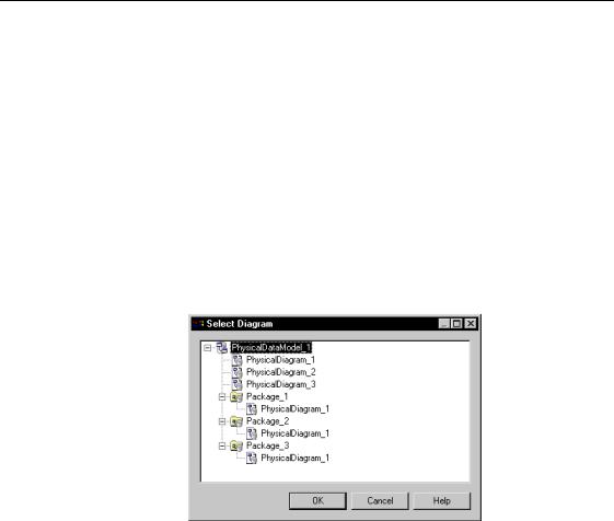
You can use the Select Diagram dialog box to navigate in the diagram |
|
hierarchy. |
|
ϖ 7R QDYLJDWH LQ WKH KLHUDUFK\ XVLQJ WKH GLDJUDP WUHH |
|
1 Right-click the diagram background and select Diagram→Select |
|
Diagram from the contextual menu. |
|
RU |
|
Select View→Diagram→ Select Diagram. |
|
The Select Diagram dialog box appears. |
2Select a diagram in the tree.
3Click OK.
The selected diagram appears in the work area.
$GGLQJ V\PEROV WR D GLDJUDP
A diagram is a view of the objects belonging to a model or to a package.
To add a symbol to a diagram you have to create a new object in the model or package to which the diagram belongs, the associated symbol appears in the diagram window.
|
PowerDesigner |

&KDSWHU 0DQDJLQJ 0RGHOV
6DYLQJ D GLDJUDP
Diagrams are saved with the model. When you save a model, you save the page scale parameters defined for each diagram.
You cannot save a diagram individually.
For more information on saving a model, see section Saving a model.
'HOHWLQJ D GLDJUDP
When you delete a diagram, you delete a view of a model or a package, this action does not affect the objects in the model or package.
ϖ7R GHOHWH D GLDJUDP
♦Select the diagram node in the Browser tree view and press the DEL key.
RU
Right-click the diagram window background and select Diagram→Delete from the contextual menu.
RU
Select View→Diagram→Delete.
General Features Guide |
|

&RQYHUWLQJ D GLDJUDP WR D SDFNDJH
&RQYHUWLQJ D GLDJUDP WR D SDFNDJH
When a package begins to reach a critical size, it is useful to reorganize it into sub-packages using diagrams.
PowerDesigner lets you convert a diagram to a package using the Convert Diagram to Package Wizard from the Tools menu. You can replace the existing diagram with a new sub-package in order to simplify the source diagram. This process moves the diagram and the objects it contains from its source package to a new sub-package. The diagram must contain objects to proceed to the conversion in the wizard.
When you convert a diagram to a package, object symbols of the diagram are always moved to the package ; the objects themselves are either moved or replaced by a shortcut.
The linking objects that you move keep their links in the target package and a shortcut is usually created in the source package. The general rule being that conceptual modeling must be preserved.
Shortcuts creation rules in PowerDesigner also apply to moving objects between packages.
For more information on shortcut creation, see chapter Managing shortcuts.
PowerDesigner lets you select the objects of the diagram you want to convert to a package using the Show Symbols dialog box. Only relevant tabs are displayed. For example, if you convert to package a diagram that only contains tables and references, only the Table tab will be available, as the reference is contained in the table definition. Besides, when you deselect two objects related with an oriented link, the link is automatically deselected (for example two classes with an association link or two entities with a relation link). Just as when you deselect a non oriented link, ending objects are automatically deselected.
Moving entities |
For entities containing data items, the following situations can occur when |
|||
|
you move the entity: |
|
|
|
|
|
|
|
|
|
'DWD LWHPV |
|
1DPHVSDFH |
0RYH UHVXOW |
|
Only used by |
|
Move within the |
The data items are moved with the |
|
selected entity |
|
same namespace |
entity |
|
|
|
|
|
|
Reused among |
|
Move within the |
Shortcuts of data items are created for |
|
different entities |
|
same namespace |
reused data items |
|
|
|
|
|
|
PowerDesigner |
|
|
|
|
|
&KDSWHU 0DQDJLQJ 0RGHOV |
|
|
|
|
|
|
|
|
|
'DWD LWHPV |
|
1DPHVSDFH |
|
0RYH UHVXOW |
|
|
|
|
||||
|
Used only by one |
|
Change |
|
Data items are copied in the other |
|
|
entity or reused |
|
namespace |
|
namespace |
|
|
among different |
|
|
|
|
|
|
entities |
|
|
|
|
|
|
|
|
|
|
|
|
6\QFKURQL]HG PRGHOV &'0 DQG 3'0 PLJUDWHG IURP YHUVLRQ
In the case of synchronized models (CDM and PDM) migrated from version 6, you need to convert both the CDM diagram and the PDM diagram into packages in order to preserve the changes made to the PDM.
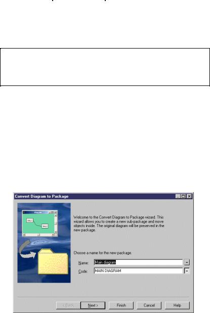
ϖ7R FRQYHUW D GLDJUDP WR D SDFNDJH
1Right-click the diagram node in the Browser and select Convert to
Package from the contextual menu.
RU
Right-click the diagram background window and select Diagram→Convert to Package from the contextual menu.
RU
Select Tools→Convert Diagram to Package.
The Convert Diagram to Package page appears. By default the subpackage takes the name of the diagram.
2Type a name and a code for the new package.
3Click Next.
General Features Guide |
|
&RQYHUWLQJ D GLDJUDP WR D SDFNDJH
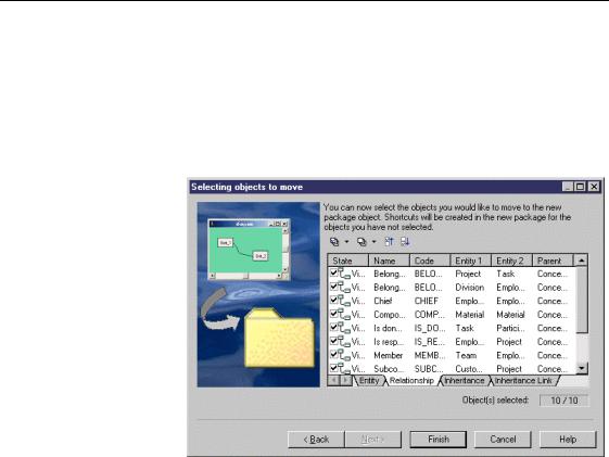
The Selecting Objects to Move page appears. It displays all relevant tabbed pages. By default, all the objects are selected.
When you deselect objects in the selection list, other object selections are not affected.
For more information on how to select items in a selection list, see section Adding an item from a selection list in chapter Using the PowerDesigner interface.
4Click Finish, if you want all the selected objects to be moved into the
sub-package.
RU
Deselect the objects you do not want to be moved to the sub-package and click Finish.
The selected objects are moved to the sub-package.
|
PowerDesigner |

&KDSWHU 0DQDJLQJ 0RGHOV
2SHQLQJ D 3RZHU'HVLJQHU VXEPRGHO DV D GLDJUDP LQ 3RZHU'HVLJQHU
|
By default, PowerDesigner 6 submodels are opened as diagrams in |
|
PowerDesigner. |
|
You can afterwards convert diagrams to packages. |
|
For more information on converting diagrams to packages, see section |
|
Converting a diagram to a package. |
Synchronize |
When you want to keep V6 conceptual and physical models synchronized, |
CDM/PDM |
you have to migrate both models. This converts V6 submodels into diagrams. |
|
For more information on the CDM and PDM migration, see section |
|
Migrating models from version 6 in the 3'0 8VHU V *XLGH. |
|
If you want to convert diagrams to packages in the models, you only have to |
|
convert the CDM diagrams to package, the generated PDM will be |
|
automatically updated and the packages will be created. |
|
ϖ 7R RSHQ D 3RZHU'HVLJQHU VXEPRGHO DV D GLDJUDP LQ |
|
3RZHU'HVLJQHU |
|
1 Select File→Open. |
|
An open file dialog box appears. |
|
2 Select or browse to the directory that contains the PowerDesigner 6 |
|
submodel. |
|
3 Select a PowerDesigner 6 file. |
|
4 Click Open. |
|
The PowerDesigner 6 submodels open as diagrams in PowerDesigner. |
General Features Guide |
|

,QWHUFKDQJLQJ PRGHOV XVLQJ ;0, IRUPDW
,QWHUFKDQJLQJ PRGHOV XVLQJ ;0, IRUPDW
PowerDesigner allows you to interchange Unified Modeling Language (UML) models between different UML tool vendors using the XML Metadata Interchange (XMI) standard file format.
XMI combines the benefits of web-based XML standard for defining, validating and sharing document formats on the Web with the benefits of the object-oriented UML. However, the current version of XMI does not support diagrams interchange.
Using XML to transmit data gives the advantage that data can be interchanged regardless of platforms.
PowerDesigner allows you not only to import XMI files so that you can use models created in collaborative modeling environments, but also allows you to export them as XMI files so that any partner can use them.
The current version of XMI is 1.1 and PowerDesigner uses the UML 1.3
DTD to generate XMI files.
When you import an XMI file in PowerDesigner, you must select an object language and the first diagram, in which you want to open the XMI file. When you export an XMI file, you save your Object-Oriented Model (OOM) under the XML format.
,PSRUWLQJ ;0, ILOHV
When you import an XMI file, you have to choose an object language and the diagram to open (class or use case). You can then select the .XML file to import.
The corresponding OOM appears in the diagram window. By default all symbols are visible in the diagram window.
ϖ7R LPSRUW ;0, ILOHV
1Select File→Import→XMI File.
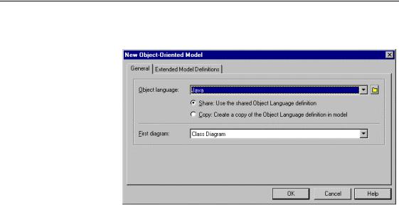
The New Object-Oriented Model dialog box appears.
For more information on object language properties, see chapter Generating for a language in the 220 8VHU V *XLGH.
2Select an object language from the Object Language dropdown listbox.
3Select either Share or Copy.
|
PowerDesigner |
&KDSWHU 0DQDJLQJ 0RGHOV
4Select the type of the first diagram (class or use case) to open in the First Diagram dropdown listbox.
5Click OK.
A standard Open dialog box appears.
6Select a .XML file and click Open.
A progress box shows the progress rate of the import process.
The General page in the Output window, located in the lower part of the PowerDesigner main window, shows the objects import order. At the end of the import process, the OOM corresponding to the imported XMI file appears in the diagram window.
([SRUWLQJ ;0, ILOHV
When you export an XMI file, you save your OOM under the XML format.
Your file can then be interchanged regardless of platforms. However symbols will be lost as only objects are exported.
ϖ7R H[SRUW ;0, ILOHV
1Select File→Export→XMI File.
A standard Save As dialog box appears.
2Type a filename for the file you want to export and click Save. A progress box shows the progress rate of the export process.
General Features Guide |
|

,QWHUFKDQJLQJ PRGHOV XVLQJ ;0, IRUPDW
The General page in the Output window, located in the lower part of the PowerDesigner main window, shows the objects export order. Your OOM is now an XMI file that you can, for example, easily share with vendors of UML modeling tools or code generator like Java, Corba or C++.
|
PowerDesigner |