- •IMPORTANT SAFETY INFORMATION
- •How to Use This Manual
- •The Big Picture
- •Knobs, Keys, and Jacks
- •The Front Panel
- •The Back Panel
- •AES/EBU Digital Audio Input/Output (Professional)
- •S/P DIF Digital Audio Input/Output (Consumer)
- •Getting Around and Altering Parameters
- •Adjusting the Brightness and Contrast of the Display
- •The "Areas" of the H8000FW
- •Understanding the Display and SOFT KEYS
- •Using the Cursor Keys, the SELECT key, the NUMERIC KEYPAD, and the KNOB
- •Ganged Parameters
- •Entering or Changing Text
- •QuickStart Or "Nearly Instant Gratification"
- •Hooking Up and Internal Routing
- •Things to Know about Routing
- •Loading Routing Configurations
- •4 Channel series Routings
- •8 Channel series Routings
- •Stereo Dual Machine Routings
- •4 channel Dual Machine Routings
- •4 Channel parallel routings
- •8 Channel parallel routings
- •Complex FireWire Routings
- •Analog & FireWire AB
- •ADAT & AES8 I/O
- •The I/O Identifier
- •Setting Input Levels
- •Effecting Things
- •"Panic" Muting
- •Loading Programs
- •Parameters
- •"Tweaking" and Saving "Tweaks"
- •Wrap Up
- •Mounting and Handling
- •Memory Cards
- •The Comprehensive Input / Output Scheme
- •Routing Configuration
- •Connecting real world inputs to the H8000FW
- •CONFIGURING THE MAIN INPUTS
- •Configuring the DSP input sources
- •Configuring the MAIN Outputs
- •Connecting to the H8000FW’s outputs
- •Configuring the outputs
- •Further Input and Output options
- •DIN 1/2 Allows the Selection of Either AES/EBU or S/P DIF for the First Digital Input Pair.
- •OPTO out – allows use of optical output connector for optical S/P DIF (H8000FW only)
- •Signal Flow Example
- •Storing and Loading Routing Configurations
- •Programs’ Effect on Routing Decisions
- •Controlling Levels
- •The Level Meters
- •Controlling the Level of the Analog and Digital Inputs
- •Input Levels, Wet/Dry Ratios, and Output Levels for Each DSP
- •Controlling the Level of the Analog and Digital Outputs
- •Digital Setup
- •Digital Setup Overview
- •Sampling Rates
- •The System Sampling Rate – A Digital Audio Primer
- •Using the Internal Clock
- •Selecting the Internal Clock’s Rate
- •The Status of The Digital Inputs When Using the Internal Clock
- •Understanding the "System Sampling Rate and External Sync Indicator" When Using the Internal Clock
- •Using an External Clock
- •Selecting the External Clock
- •The Status of the Digital I/Os When Using the External Clock
- •Understanding the "System Sampling Rate and External Sync Indicator" When Using the External Clock
- •Sample Rate Conversion (SRC)
- •Word Clock Termination
- •Word Length (Bits)
- •Input Word Length
- •Output Word Length
- •Bypassing and Muting
- •System Bypass
- •Machine Bypass
- •External Controllers
- •Setting Up the External Controllers
- •Foot Pedals 1 and 2
- •MIDI Setup
- •External Modulation and Trigger Menu Pages
- •"Manually" Selecting an External Controller for Modulation
- •"Manually" Selecting the External Controller for Triggers
- •External Controller Selection
- •Parameters Common to Both External Modulation and External Trigger Menu Pages.
- •MIDI Running Status
- •Automatically" Selecting a MIDI External Controller
- •Scaling the External Controller
- •The Concept Behind "Redirection" - External Assigns 1-8 and Trigs 1 & 2
- •Remote Controlling Parameters
- •Remote Controlling Triggers
- •MIDI Groups
- •Program Load, Save, Delete, Etc.
- •Categorizing Programs
- •Categorized by Effects Type
- •Categorized by Similar Programs (Banks)
- •Loading Programs
- •Loading a Program Remotely
- •Loading a Program Via a MIDI Program Change Message
- •Triggering the Next or Previous Program to Load
- •Saving a Program
- •Copying Programs
- •The "Size" of a Program and Its Ramifications for Storage
- •Updating a Program
- •Renaming a Program
- •Deleting a Program
- •Parameters
- •System Tempo
- •System Timer
- •Taps
- •Textblocks
- •Graphics and Curves
- •Storing and Loading Setups
- •Miscellaneous Setup Options
- •Transmitting and receiving Data
- •Setting Up the Serial Port
- •Dumping Data and Receiving Data Dumps
- •Controlling One H8000FW from Another H8000FW
- •Sending A Program From One the H8000FW to Another
- •Sequencing With MIDI
- •Connecting user-supplied crystals and external clocks
- •Service and Start-Up Options
- •Fixing Internal Memory Problems
- •Fixing PCMCIA SRAM Memory Card Problems
- •Changing the Internal Battery
- •Clear Setup
- •Software Version and Accessories
- •Start-Up Options
- •Making connections between the H8000FW and the computer.
- •Setting the sample rate and buffer size for the system
- •Synchronizing connected audio devices
- •Configuring the H8000FW for Throughput
- •Device Settings
- •Device Description
- •Device nickname
- •Measured Sampling Rate
- •Status
- •Global Settings - Bus Page
- •Master
- •Sample Rate
- •Sync Source
- •Buffer Size
- •Unique ID
- •Operation Mode
- •Global Settings - WDM Page
- •Set WDM Channel Maps
- •Global Settings - DPC Page
- •Global Settings -System Page
- •Global Settings -Info Page
- •PAL, Driver version
- •Viewing the H8000FW’s Configuration
- •Setting Up the H8000FW for Default Audio Output
- •Configuring the H8000FW for Output with Logic Pro
- •Creating an Aggregate Audio Device
- •Routing Audio to the H8000FW
- •Configuring Logic Pro for H8000FW Input and Output
- •An Example of Using Logic Pro with the H8000FW
- •Step-by-Step Descriptions of the Routing Process Flow
- •Sample Rates
- •Frequency Response
- •Digital Inputs/Outputs
- •Analog Input (XLR Balanced Inputs)
- •Analog Output
- •Remote Control Inputs
- •Remote Control Outputs
- •MIDI Connections
- •Memory Card Interface
- •Factory Preset Capabilities (at 48k sampling)
- •Power
- •Size
- •Weight:
Using the Cursor Keys, the SELECT key, the NUMERIC KEYPAD, and the KNOB
We use the CURSOR keys, the KNOB, the SELECT key, and the NUMERIC KEYPAD to navigate and manipulate the menu pages found in the PARAMETER, Patch Editor, LEVELS, BYPASS, and SETUP areas. We’ll discuss their use in the PROGRAM and Routing Storage areas in a bit.
Use of the cursor keys is straightforward. The LEFT and RIGHT CURSOR keys move the cursor left and right, respectively. The UP and DOWN CURSOR keys move the cursor up and down, respectively. (Go figure...)
Use the KNOB, NUMERIC KEYPAD, or the / keys to alter the value of a numeric parameter. For example, spin the KNOB on this screen to change the value of Mix or enter a new value
directly with the NUMERIC KEYPAD (pressing ENT when you’re done).
Use the KNOB or the / keys to alter the value of a text parameter. For example, spin the KNOB or press the key to change Shape from Sine to Triangle on this screen.
Numeric parameters and text parameters cover 99% of the parameters you’ll see in the H8000FW, but there are a few more esoteric parameters you’ll encounter. One such oddball is the "trigger" parameter. You place the cursor over a trigger parameter, and trigger it by pressing SELECT. It will trigger something (no doubt fascinating) to happen. Other oddballs include "Taps" and "Graphics."
See System Tempo on page 132.
See Graphics and Curves on page 135.
The left and right cursor keys behave differently than you might expect in the PROGRAM area. Please see Loading Programs on page 37 for a brief introduction, and Loading Programs on page 123 for a more detailed discussion.
See wheel speed on page 138.
19
Ganged Parameters
In some cases there are multiple, related parameters that are usually adjusted together. To make such "mass adjustments" easy, a feature exists that gangs parameters together. The outputs menu page in the SETUP area contains a good example of ganged parameters. The purpose of this menu page is to assign signals to
the AES/EBU digital outputs. Such assignments are typically made in quad or stereo gangs. So, all four parameters are initially ganged together. Spin the KNOB and all four values change.
Now, let’s say you only want to change the assignments to DIG1 and DIG2. Press the DOWN CURSOR key to "un-gang" DIG3 and DIG4. Now spin the KNOB; only the values for DIG1 and DIG2 change.
Going further, let’s say you only want to change the value of DIG1. Again, press the DOWN CURSOR key to "un-gang" DIG2. Now, spin the KNOB - only the value of DIG1 changes. Press the DOWN CURSOR key repeatedly to cycle through the various gang possibilities: next DIG2 alone is selected, then DIG3 and DIG4 are ganged together, then DIG3 is alone, then DIG4 is alone, and lastly we arrive at our starting point - all four parameters are ganged together. Gangs are much easier to use than to describe, so take a minute and play with the gangs on this menu page. You will find gangs sprinkled liberally throughout the H8000FW as their presence facilitates many tasks.
Entering or Changing Text
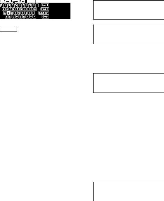
In some menus, it will be necessary to enter or change text. For example, you will often change text when saving a new program. The method by which this is done is straightforward, albeit a
bit tedious. To play along, go to the PROGRAM area and press the <Save as> SOFT KEY. (You may have to press the PROGRAM key a second time to see it.) Move the cursor over the rename field and press SELECT.
Here’s how it works:
The upper-left portion of the display contains the text that’s being changed. Here we’ve entered "I Can Type Fas..." - we’re not quite done.
20