


The I/O Identifier
While each DSP has eight inputs and eight outputs, it’s not necessarily the case that every program will utilize all eight inputs or all eight outputs of the DSP it’s running on. Every program is unique and uses only the number of inputs and outputs that are necessary for its function. For instance, a program that synthesized sound would not need any inputs!
A program that modulated one stereo signal with another would need four inputs (two for the carrier and two for the modulator) but only two outputs (for the result of the modulation). Again, the function of a program determines how many inputs and outputs are utilized on the DSP running the program.
Notice that to the right of every program name in the PROGRAM area is a two-digit number (press the PROGRAM key to get there). This two-digit number is known as the "I/O
Identifier." In the case of the program "BasicRoom" shown to the right, the two digit number is "24." In the case of the program "Compressor_8" shown to the right, the two-digit number is "88." The first digit indicates how many inputs are utilized, and the second digit indicates how many outputs are utilized. If the "I/O Identifier" for a program were "13," DSP input 1 would be used while inputs 2 through 8 were dead, and DSP outputs 1, 2, and 3 would be used while outputs 4 through 8 were dead. A program will utilize the same number of inputs and outputs regardless of whether it is loaded on DSP A or DSP B.
A small number of programs have no I/O identifier. See .
If the I/O Identifier is not visible on page 69 for more information.
34
Those DSP inputs or outputs that are not used by the program are "dead" - no signals are passed by them. Knowing which inputs and outputs a program uses can affect which routing configuration you choose to use. You probably wouldn’t want to place a program that only utilized two inputs after a program that utilized four outputs because two of those outputs would be connected to "dead" inputs.
the signals at the two outputs connected to "dead" inputs would be "lost.") diagram above.
It’s important for you to think about which inputs and which outputs from DSP A and DSP B are "dead" in the context of the routing configuration you’ve chosen. Nevertheless, things usually work out more easily than this brief warning might cause you to believe!
For more information on this topic, including examples, see Programs’ Effect on Routing Decisions on page
69.
35
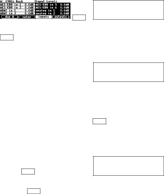
Setting Input Levels
As we’re sure you know, getting a high, but not distorted, signal at every point in a signal path is essential. The Level Meters help us to achieve this goal. In the LEVELS area go to the meter
menu page to reach this screen. Adjust Source (with the KNOB or the INC/DEC keys) to inputs. The eight Level Meters now reflect input levels of the signals defined on the inputs menu pages in the SETUP area.
In this cursory introduction, we only fiddle with the levels at the inputs but, rest assured, you can change levels almost anywhere in the
signal path.
See:
Controlling the Level of the Analog and Digital Inputs on page 73.
Input Levels, Wet/Dry Ratios, and Output Levels for Each DSP on page 75.
Controlling the Level of the Analog and Digital Outputs on page 76.
Of course, it’s always best to optimize levels at their source (leaving the H8000FW’s boost/cut at 0dB). But if you can’t, then go to the inputs menu page in the LEVELS area. If you’re using the analog inputs, press it twice so that only the analog input levels are shown. Here you can boost/cut the analog inputs by +30dB/-90dB before they are digitally converted - setting the gain before the converters gives the best characteristics.
(H8000 menu page shown, H8000FW has adjustments for all four analog inputs.)
You can cut the analog inputs after digital conversion and the digital inputs by 0db/-100dB on the first inputs page
different depending on your routing configuration and will definitely
look different if you have an H8000FW). Assuming you set the Source of the Level Meters to inputs on the meter menu page in the LEVELS area, the meters reflect the input levels after the boost/cut is applied. You want the loudest portions of the signal to approach, but not reach, the red "clip" LED at the top of the Level Meters. If you do clip a signal, you won’t hurt the H8000FW, but you may hurt your chances for career advancement - a clipped signal typically sounds nasty.
For more information on setting input levels see Controlling the Level of the Analog and Digital Inputs on page 73.
36