

Loading Programs
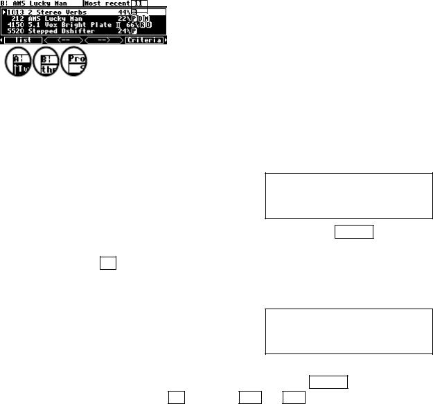
Programs are loaded by first selecting a program to load in the PROGRAM area. You select a program to load by sorting through the available programs (see the preceding section). Use the up and down CURSOR keys or the KNOB to highlight the program you want to load on the list menu page.
It’s important to note that the program will be loaded into the currently displayed DSP as indicated by the upper left-hand corner of the display.
If you want to load a "non-monolithic" program into the DSP not currently displayed, you need to press the PROCESSOR A/B key. If the H8000FW is currently running a monolithic program (no "A:" or "B:" in the upper left corner), a "non-monolithic" program will load into DSP A and the "Thru'" program will be loaded into DSP B.
Some larger programs, those not marked with a "96," will be unavailable for loading when the system is using a high sampling rate. Programs using the (large) Sampler and Longdelay
modules cannot be loaded on DSP B. If Show is set to any on the Criteria menu page in the PROGRAM area, these "unloadable" programs will be displayed with a line through them on the list menu page. To avoid seeing these programs when they can’t be loaded, set Show to the default setting loadable.
The last few programs that were loaded are also saved in the "Most recent" group. This means that you can quickly revisit the programs that you are currently using, without having to look
through all the programs to find them again. You can find this list (and reload those programs from it) by setting Search By to User Grp on the Criteria menu page in the PROGRAM area. Then go to list and use the < - - and - - > SOFT KEYS to find the Most recent list - it is actually the first Usergroup and is maintained by the system.
Loading a Program Remotely
There are two ways to load programs remotely. The first is via a MIDI program change message, and the second is by triggering the H8000FW to load the next or previous program in the current bank. Let’s discuss them in turn, shall we?
123
Loading a Program Via a MIDI Program Change Message
The normal way to load a program remotely is by means of a MIDI Program Change message. A MIDI Program Change message can be sent by a MIDI keyboard, a MIDI sequencer, or a MIDI foot pedal. Using a MIDI foot pedal on stage makes loading programs a breeze.
Unfortunately, MIDI Program Change only supports programs numbered from 0 to 127. Since the H8000FW has well over a thousand programs, each with a threeor four-digit number, this presents a small problem. One way one to get around this limitation is by using a "MIDI map" to translate between program numbers with MIDI Program Change numbers.
The H8000FW can use its Usergroups as MIDI maps. Each program in a Usergroup can have a Program Change number associated with it, so that if this number is sent by a MIDI controller,
that program will be loaded. If a program exists in both 48kHz and 96kHz versions, the one most appropriate to the current sample rate setting will be chosen.
See Categorized by You (User Groups) on page 118.
This is extremely handy! You can use the usergrp menu page in the PROGRAM area to assign programs to any of ten "user groups" in User Memory and another ten on the Memory Card. Maybe you want to "group" all the programs associated with a certain project for ease of access later on. Maybe you want to keep track of programs you really like.
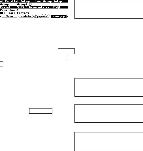
First use the KNOB to select the group you want to change on the top line.
Then, to find an empty place to put it, use the KNOB on the third line (Prog Chng) until the Preset in the second line shows <none> or
<empty>.
Then, on the second line, choose the program you want to include in the group. Here we’ve included the program 4_ReverseTetra in Group7. You’ll see that you can usefully
organize programs via user groups! To remove a program from the Usergroup, either turn the wheel at the second line to select another one, or type 0 ENT on the numeric keypad to set it to <empty>.
124
The second line of this screen shows the programs according to the Search and Sort options on the Criteria page. The wheel or keypad can be used to move through them in the same way as on the list screen. A tip - it's easier to find things by name using the knob if you have previously set Sort By to Name on the Criteria page.
Note that Usergroup 1 is a Factory group, with a selection of the more interesting programs in the H8000FW. This group cannot be changed. The presets included in it can be found in the H8000FW Presets Manual.
The third line, Prog Chng allows you to assign a MIDI Program Change value (0-127) to each program in a Usergroup. This allows Usergroups to be used as MIDI maps, enabling their members to be loaded via MIDI program change messages. If you are not using the Usergroup as a MIDI map, think of this as a "slot" number.
The bottom line of this screen also appears on the SETUP/MIDI screen (shown below) and tells you which group is the current active MIDI map. If the selected group (Group 7 in the
example shown above) is the active one, it will show (MIDI map).
In order for the MIDI map feature to be operational, the parameter MIDI on the first midi menu page in the SETUP area must be set to enabled, and the parameter MIDI map on
that menu page must be set to the number of the Usergroup that you wish to use as the MIDI map. The default setting is that of the Factory Usergroup, group 1.
If no MIDI map is selected (none), the program loaded by a MIDI program change message will be in the same bank as the one currently selected on the visible DSP.
For example, the PROGRAM screen to the right shows that program 1410 is currently selected for DSP A. This means that the current bank is 14, covering programs from 1400 to 1499. If a MIDI
program change message of 32 is received, the H8000FW will load program 1432 into DSP A.
If the parameter omni mode is set to on, the program will be loaded into the current DSP.
125

Alternatively, if omni mode is off, a MIDI Program Change message sent using the base channel will cause the program to be loaded in DSP A, while a MIDI Program Change message
sent using the channel one greater than the base channel will cause the program to be loaded in DSP B. The system will be switched to A or B as appropriate, just as if the PROCESSOR A/B button were pressed. The normal rules of course apply, so that if you try to load a "monolithic" program, it will always load into DSP A.
Note that MIDI Controller #0 (Bank Change) will allow you to set the bank remotely.
All the above parameters are found on the "second" midi/ext menu page in the SETUP area.
Note: To aid in troubleshooting, you can use the BUSY LED as a "MIDI chaser." With the Memory Card removed, any MIDI signals sent to the MIDI In port cause the BUSY LED to flash. If you’re trying to send MIDI Program Change messages to the H8000FW, but the BUSY LED isn’t flashing when you do (and the Memory Card is removed!), you know something is wrong with the connections outside the H8000FW.
126