

midiclk outWill make the H8000FW output a MIDI clock signal that represents its internal tempo (SETUP/tempo). This is a high accuracy signal to which other equipment can synchronize.
That’s it for MIDI globals. If you press the midi SOFT KEY one more time, you’ll see parameters pertaining to the serial port’s setup.
See Setting Up the Serial Port on page 139.
EXTERNAL MODULATION AND TRIGGER MENU PAGES
Many aspects of the H8000FW’s operation can be controlled by "external" signals. These "external" signals include MIDI signals and signals at the rear panel foot pedal jacks 1 and 2 (see External Controllers on page 92 to set these controllers up). External "modulation" involves altering a parameter value over a range of values. For example, you could modulate a delay from 5 milliseconds to 25 milliseconds. At different points in time, the delay will be 5 milliseconds, 25 milliseconds, and all of the values in-between. An external "trigger," on the other hand, has only two states. It is not continuous. For example, you could trigger a gate to open. The gate can be either open or closed. A trigger switches the parameter from one state to the other.
The various external modulation and trigger menu pages you will encounter are all variations on a common theme. Although the length of this section might lead you to think otherwise, all you’re really doing on these menu pages is selecting the external controller that will modulate or trigger a parameter. If the external controller you select involves MIDI, then you will also have to deal with MIDI channels and (possibly) MIDI control numbers. This adds length to our discussion, but it shouldn’t add complexity.
In the case of external modulation menu pages, we’re doing one more thing: we’re scaling the external controller to suit the range of modulation we would like. Again, the concept is simple, but we’ll have to get a little wordy in the process of describing it. Apologies . . .
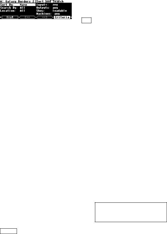
For the sake of providing an example, we’re going to externally modulate the knob parameter found in the program Interface Modules. To load it, set the parameters on the
Criteria menu page in the SETUP area as shown here.
96

Then use the left and right CURSOR keys to skip through the programs by their first letter to the programs that begin with "i". Then use the up and down CURSOR keys to find the program
Interface Modules and press the SELECT key.
This program was designed for folks who are interested in creating their own programs (see the separate programming manual). As such, knob doesn’t do anything useful, but it will serve us well for the purposes of this demonstration.
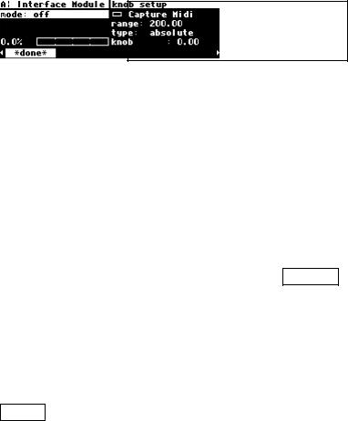
With the cursor highlighting knob on the inputs menu page in the LEVELS area, press and hold the SELECT key until the external modulation menu page shown to the right
appears. The "SELECT key trick" is how you "remote control" any parameter in the H8000FW and is discussed in depth on page 111. For now, we have a convenient method for getting you to an external modulation menu page. You will also find "explicit" external modulation menu pages in the PARAMETER area (ones that don’t require you to press SELECT to see them!) .
See Remote Controlling Parameters on page 111 if you’re really curious.
97
"Manually" Selecting an External Controller for Modulation
The first parameter, mode, selects the actual external controller that will do the modulating. Our choices are as follows (some are discussed in the section immediately following this one):
off No external modulation at all.
highThis isn’t really a modulator (it doesn’t evolve through time). It pins the parameter at its highest modulation value.
mid This pins the parameter at its middle modulation value.
low This pins the parameter at its lowest modulation value.
assign 1, 2, ..., 8, Trig 1&2
These are "placeholders" that are assigned to actual external modulators on the external menu page in the SETUP area. Until you understand the concept of "redirection" discussed below don’t pay any attention to these.
You can read about redirection in The Concept Behind "Redirection" - External Assigns 1-8 and Trigs 1 & 2
on page 106.
pedal 1 & 2 The input from the pedals at the rear panel foot pedal jacks 1 and 2. These jacks are setup on the pedals menu page in the SETUP area.
See Foot Pedals 1 and 2 on page 92 to "set them up."
tip 1 & 2, ring 1 & 2, and tip & ring 1 & 2
When a pedal input is used as a switch input, it can operate in one of two modes, supporting either 2 switches or 3 switches. If any controller references "tip&ring" for a given socket, that socket will be in "3 switch" mode, otherwise it will be in "2 switch" mode.
In "2 switch" mode:
"tip" is high when a switch connected between tip and sleeve is closed.
"ring" is high when a switch connected between ring and sleeve is closed.
To give an added control input, a third switch may be connected so as to connect both tip and ring to sleeve. This will require a 2 pole switch or a few diodes. Alternatively, the same results may be obtained by pressing the first two switches simultaneously to simulate the third switch. (See drawing on page 101.)
98

In "3 switch" mode:
"tip" is high when a switch connected between tip and sleeve is closed and the third switch is open.
"ring" is high when a switch connected between ring and sleeve is closed and the third switch is open.
"tip&ring" is high when the third switch is closed.
mod wheel |
MIDI control message 1 - typically assigned to the mod wheel on a |
|
MIDI keyboard. |
chan pressure |
MIDI channel pressure message. |
pitch wheel |
MIDI pitch bend message. |
breath con |
MIDI control message 2 - typically assigned to the breath controller |
|
on a MIDI keyboard. |
foot con |
MIDI control message 4 - typically assigned to the foot controller on |
|
a MIDI keyboard. |
Portamento |
MIDI control message 5 - typically assigned to portamento. |
volume |
MIDI control message 7 - typically assigned to volume changes. |
balance |
MIDI control message 8 - typically assigned to balance. |
pan |
MIDI control message 10 - typically assigned to panning. |
expression |
MIDI control message 11 - typically assigned to the expression |
|
controller on a MIDI keyboard. |
general 1, 2, 3, and 4
MIDI control messages 16, 17, 18, and 19.
MIDI double Allows selection of any MIDI control number with very fine quantization. Input range is 0 to 16383. A third parameter appears, con, which selects the
controller number to be used. Your choices for con are 0 to 31. The MIDI control number con will pass the "coarse" value for the modulation and the MIDI control number con + 32 will pass the "fine" value for the modulation.
99