


When type is set to unipolar and the external controller is all the way up, the parameter will take on a value determined by the origin and the range. Here 10% plus 66% = 76 %.
When type is set to bipolar, the parameter takes on the value of the origin when the external controller is halfway up (or halfway down if you're a pessimist).
When type is set to min/max and the external controller is all the way up, the parameter will take on a value determined by maximum, 66 % in this case. When the external controller is all the way down, the parameter will take on a value
determined by minimum. You can toggle the display between showing minimum and maximum by hitting SELECT.
The final parameter on the external modulation menu page is just a duplicate of the parameter you’re modulating. Its value reflects the applied external modulation, so you can see the result of all your futzing as you futz (the external modulation’s value will be ADDED to the parameter’s value). Additionally, you can adjust the value of the parameter while you futz as we did in the example above. If you modulate a gang of four or more parameters, they will not be shown on the external modulation menu page because there isn’t enough room to fit them all!
In practice, scaling is even more flexible than we've described here. It's one of those things that's much easier to do than to describe!
The Concept Behind "Redirection" - External Assigns 1-8 and Trigs 1 & 2
"Redirection" allows a program developer to use an external controller in his program, while allowing one to assign which actual external controller is used at a later time. An external controller "placeholder" is used in the program, and you fill in a specific external controller for that "placeholder." Redirection also allows you to select a "placeholder" on an external modulation or trigger menu page. If you select the same "placeholder" on several external modulation or trigger menu pages, you can change the actual external controller that fills that "placeholder" by making one change. If redirection didn’t exist, you would need to go to each and every one of those external modulation or trigger menu pages and change the actual external controller manually. Wow ! That’s pretty abstract. If it doesn’t make sense yet, read through this section and then re-read this paragraph.
There are eight external assignment "placeholders": assign 1, assign 2, ..., assign 8. There are two external trigger "placeholders": trig 1 and trig 2.
106

These "placeholders" are selected as the mode on external modulation or trigger menu pages littered throughout the H8000FW. For example, assign 3 can be assigned here. . .
And here. . .
And here. . .
And anywhere. . . You see that a single "placeholder" can modulate or trigger many different parameters.
A single "placeholder" is "filled" by an actual external controller at one place: the external menu page in the SETUP area. A single "placeholder" is "filled" by only one actual
external controller. In the example screen shown to the right, the actual external controller mod wheel has been selected to "fill" the "placeholder" assign 3.
Now all of the "and here. . ." example screens shown above would actually be modulated by the mod wheel!
Moreover, the value in parentheses above,
(low), would change to (mod wheel).
The external menu page is "stacked." Press the external SOFT KEY repeatedly to cycle through menu pages for assign 1, assign 2, assign 3,
..., assign 8, trig 1, and trig 2. These menu pages
behave just like those that were discussed in External Modulation and Trigger Menu Pages on page 96, except that there is no range parameter. This makes sense because a single "placeholder" can be selected to externally control a multitude of parameters. "Scaling" is done on the external modulation or trigger menu pages littered throughout the H8000FW that have as their mode the "placeholder."
107
So, "redirection" allows you to configure your external modulation and trigger menu pages to suit the particulars of your studio/rack setup. Let’s say you frequently use a foot pedal, the pitch wheel, the mod wheel, and MIDI controller 10 (pan) to do external modulations and MIDI Note On and MIDI Start to do external triggers. Instead of explicitly assigning all of these external controllers on external modulation and trigger menu pages in the programs that you save, you could instead assign assign 1, assign 2, assign 3, ..., assign 8, trig 1, and trig 2. Then go to the external menu page in the SETUP area and assign the foot pedal to assign 1, the pitch wheel to assign 2, the mod wheel to assign 3, MIDI controller 10 to assign 4, MIDI note on to trig 1, and MIDI start to trig 2.
Here are the benefits: If you take the H8000FW on the road or to another studio and need to use different external controllers, you don’t have to re-edit all of the programs you use. Instead, just reassign the "placeholders." If you get a new sequencer that has different "convenient" controllers than the ones you’ve been using, you don’t have to reedit all of the programs you use. Instead. . . All right. You get the idea.
We should run through an example to make sure you’re clear about what’s going on here. While you're going to use placeholders to modulate system-level parameters, you would normally use them to modulate parameters in programs such as feedback, chorus level, pitch shift, etc.
Let’s highlight the first digital input on the inputs menu page in the LEVELS area (in this case the first digital input is S/P DIF in 1).
Remember to press the DOWN CURSOR key to "un-gang" parameters.
See Ganged Parameters on page 20 for more about "gangs."
Press and hold the SELECT key for one second.
The menu page to the right appears.
To change the "one second hold time," see
Miscellaneous Setup Options on page 138.
Set the mode to assign 3. Press the *done* SOFT KEY to save the assignment and return to the inputs menu page in the LEVELS area.
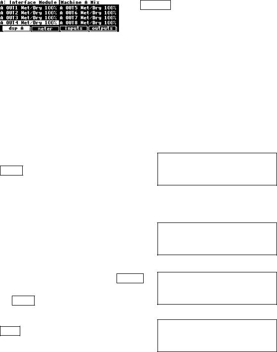
Next, let’s highlight A OUT4 Wet/Dry on the dsp A menu page in the LEVELS area. Remember to press the DOWN CURSOR key to "un-gang" parameters.
108
Press and hold the SELECT key for one second. Set the mode to assign 3. Press the *done*
to exit.
To change the "one second hold time," see
Miscellaneous Setup Options on page 138.
At this point, we’ve assigned the "placeholder" mod 3 to modulate both S/P DIF in 1 and A OUT4 Wet/Dry. Now, let’s "fill in" this "placeholder" with an actual external controller.
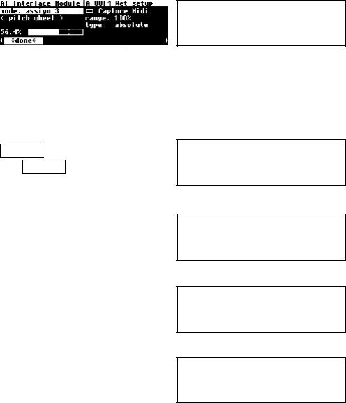
Go to the external menu page in the SETUP area. Press the external SOFT KEY repeatedly until you see "assign 3 setup" in the upper right-hand corner.
You can set mode to anything you like; we’re going to set it to pitch wheel on channel omni (the omni parameter on the [midi] menu page in the
SETUP area needs to be set to off in order to assign a specific channel ).
Now, when you move the pitch wheel both S/P
DIF in 1 and A OUT4 Wet/Dry are modulated!
(Select the MIDI base channel on the [midi] menu page in the SETUP area.)
If you actually followed along with your H8000FW, you’d be wise to go back to these two parameters and set mode to off, so that your input levels and wet/dry ratios don’t start doing freaky things in response to the pitch wheel in the future!
The very first time you switch on the H8000FW, you will find that assigns 1-8 are set to high - this is so that any programs which use one of these as a volume control input are not silenced. It is recommended, for the same reason, that, if you change these settings and then want to remove the change, you set them back to high, rather than to off.
109
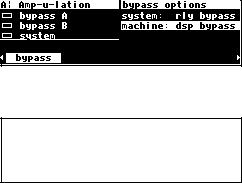
Remote Controlling the Bypass Functions
It is often necessary to be able to remote control the system bypass function. For this reason a special controller has been set up for this purpose. It can be found under
SETUP/external. Press this key a few times until you come to it.
Another way to remote control system bypass, which also applies to machine A and machine B bypass, is to use the SELECT and hold approach on the LEVELS/bypass page, treating it as if it were any other parameter.
See Remote Controlling Parameters on page 111.
110