


Making connections between the H8000FW and the computer.
All recent Macs and many PCs support FireWire. Those PCs that do not support FireWire can usually be upgraded with an inexpensive plug-in card.
The H8000FW is connected to the computer using an IEEE1394A FireWire cable which is widely available from computer stores and typically ranges in length between 3 and 15 feet. Cables longer than 15 feet (4.5m) are not supported by FireWire without the use of special adaptors. This cable can be connected to either FireWire connector on the H8000FW, allowing the other one to connect to a following FireWire device if desired.
While FireWire is designed to be hot-pluggable (meaning that it can be connected to powered-on systems), Eventide recommends that where possible it be connected between units when their power is switched off. The reason for this is to avoid certain rare conditions which can damage the unit being connected.
Setting the sample rate and buffer size for the system
A number of settings can be made that affect the performance of your system. The first of these is sample rate, which is the rate at which the audio is converted from the analog world to discrete digital values (or the other way around). This is usually expressed in kHz or samples per second.
The sample rate is normally defined by the computer operating system or by the workstation application and can be set from a menu or dialog box. See the manual for your application to find out how to change the sample rate. You should not change the sample rate directly from the H8000FW when it is connected to the computer as this can cause problems for some applications – change it on the computer and the computer will automatically change the H8000FW setting where necessary. Higher sample rates give better audio performance but use more disk space for recording and place heavier demands upon the computer.
The buffer size setting determines the latency of the system. Latency in this context is a measure of the delay introduced by sending audio to and from a computer and an external device such as the H8000FW.
To help explain this, an analogy may be helpful. Picture a large pile of coal representing the digital information stored in the computer. Each piece is one digital value. The job here is to fill buckets (the buffers) with coal from the pile, and pass them to a colleague who then empties them into a chute leading to the outside world. The chute must be kept
partially full but not allowed to overflow. The chute may be thought of as the feed to an 156

external digital to analog converter feeding a speaker, while the passing of the buckets represents the FireWire connection.
So, if the chute becomes empty the speaker will pop or click, while if it overflows things may get in the wrong order. It also takes time for any given piece of coal to get from the pile to the chute, as the buckets have to be filled and emptied before this can happen. This time is the latency mentioned above.
It will be apparent that the size of the buckets directly affects the latency, as smaller buckets can be filled and emptied more quickly. But, to avoid the chute becoming empty (bad!), they will have to be passed more quickly, which may be tiring. So, there is probably an optimum size for these buckets, to provide a good compromise between the latency on one side, and the energy requirement (computer power) needed to pass them.
Enough of coal for now. The latency is usually almost directly proportional to the buffer size, but the use of small buffers requires more computer power. The default setting is usually a good compromise, but if low latency is important and you have a fast computer it may pay to reduce it.
Some simple math for those so inclined: if you are running at 48kHz, a 1024 sample buffer will introduce a latency in the order of 1024/48000 seconds, or 21mS (milliseconds). So, to send and return to a FireWire device will take 42mS, which is noticeable. Those systems that offer delay compensation can resolve the problem painlessly, but otherwise the use of smaller buffers is worth considering.
Synchronizing connected audio devices
For audio purposes, a computer can be thought of as a device that shuffles processed data between its disk drives, memory and peripherals. As such, it neither has nor needs the concept of a sample rate (except for calculating delays or filters and such-like). This concept only becomes necessary when it is necessary to output audio to or from the outside world, in which case it is set by the hardware conversion devices.
Things become more complex when you have more than one device that cares about the sample rate because if a device gets data at the wrong sample rate it will have to drop samples or insert extra samples to keep up. This will cause clicks or distortion, depending on its severity. To avoid this, we allow one device, known henceforth as the clock master, to define the sample rate and any other devices have to follow its lead.
157
If you are using just one external audio device (or an internal one such as a sound card) everything is easy. This device becomes the clock master (usually automatically) and the computer does what it has to do.
If you have more than one device, commonly a sound card and one or more external audio thingies, life is more complicated. As before, you have to define one device as being the clock master and must synchronize the others to it so that they all run at the same sample rate. This is made more difficult by the fact that some devices (sound cards especially) cannot accept synchronization and must be made the clock master, obliging the other devices to be synchronized to them. All audio devices used together in a system
MUST be synchronized to run at the same sample rate.
Synchronization is typically achieved by either hardware or software measures:
Hardware synchronization is achieved by connecting AES, S/P DIF or Wordclock cables from the outputs of the clock master to a corresponding input of the other devices and configuring these devices to use this signal as a sync source.
Software synchronization employs the use of sample rate conversion (which uses a lot of computer power) to make disparate devices compatible with the master sample rate. It is available on Macs when creating Aggregate Devices, or on some Windows applications using WDM drivers. Again, see your computer manuals for more details on these.
The FireWire link contains a sample clock to which the H8000FW can be synchronized if all other approaches fail, but this is not recommended except as a last resort as the quality of this clock is not high and it can increase jitter or other bad things. Note that on Macs this is not always available.
So, to sum up:
One audio hardware device must be configured as the clock master
Any other audio devices in the system must be synchronized to the clock master by (preferably) hardware or software means.
158

I n s t a l l i n g D r i v e r s o n Yo u r P C
This section describes how to install the software drivers required to operate the H8000FW Multi-Channel Effects System with your Windows XP or Vista-based PC. Those hip Mac people should skip ahead.
If you are updating your drivers with new ones, read the release notes supplied with the update. If an H8000FW update is also required, perform this before continuing.
Your Windows-XP or Vista should have the latest service packs installed. If you are not sure, go to http://update.microsoft.com/windowsupdate to check that your PC is up to date. We recommend that you keep your machine up to the standard Microsoft specification – we cannot guarantee results with outdated, beta or experimental versions of Windows.
You may see cosmetic differences between the screens below and those on your computer, depending on its settings and operating system. You may also see interchangeable references to either “H8000 Audio” or “Eventide Dice.”
Before starting, be sure your PC is equipped with a Firewire port. If your PC did not come equipped with a Firewire port, you must purchase a Firewire PCI card and install it. See the recommendations under Check your FireWire Card on page 173.
Leave the FireWire cable unconnected at this time.
Locate the drivers file, EventideInstaller.exe (setup.exe on older drivers). This will either be on the CD supplied with your H8000FW or contained within a compressed zip file downloaded from the Eventide Web site. If the latter, open (extract) the zip file and copy the .exe file to your hard disk. The latest version of the driver can always be found on the Web Site.
159

Run the EventideInstaller.exe file by clicking on it. You will see the screen below. The long number after “Dice” may be different.
Follow the instructions and hit Next ..
Unless you have a real reason to do otherwise, accept the suggested folder and hit next. If you get “Folder Exists” message, answer “Yes”.
160
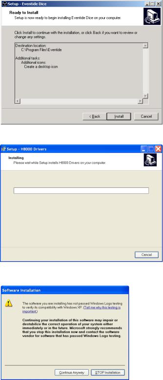
Leave the “Create a ..” box checked and hit Next. When you see the box below, hit
Install.
Please wait ….
After about a minute you will see the following screen. Hit Continue ….
(For the easily frightened - Windows Logo testing has various requirements that are inappropriate for professional audio equipment so these drivers do not need to comply).
A browser window will also open, showing the release notes for this version of the drivers. These show the issues resolved by this and previous driver releases. They may appear rather technical but can provide useful information.
161
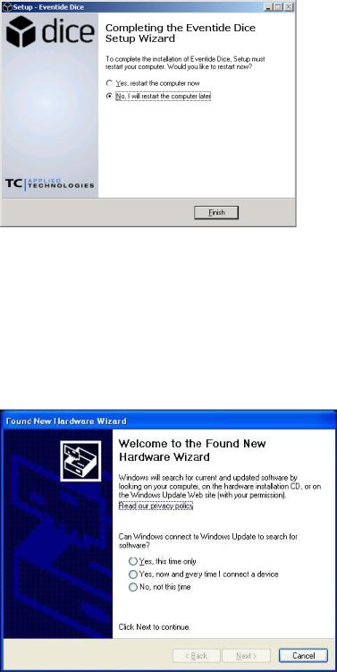
After about a minute, you will see the box below. You MUST restart your computer before continuing, but need not do it immediately if you have other work to do.
Insert the Firewire cable into your PC’s Firewire port, and the H8000FW’s Firewire port, which is located directly to the right of the AC power cord port.
Turn on the Eventide H8000FW. (Windows XP will generate a two-tone audio signal when it recognizes a Firewire connection. Similarly, when a connection is disabled or broken, it will sound a reverse two-tone signal).
Windows will automatically detect that a new hardware device is connected., and display the first New Hardware Wizard screen:
162

Click the No, not this time radio button, followed by the Next button.
The second Wizard screen now displays:
Make sure Install the software automatically is selected, then click Next.
The following screen may annoyingly display again. If it does, select Continue
Anyway.
163
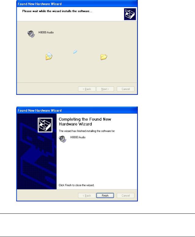
The installation now proceeds ……
When the driver is successfully installed, the following screen displays:
Now click Finish. All done. Time for a nice cup of tea.
Note: If for any reason the drivers did not install properly, unplug your Firewire cable from your PC, wait several seconds, and insert it again. You will be prompted by the New Hardware Wizard to insert your drivers CD as outlined above. Go through the process again until you receive the Windows confirmation message that all drivers were successfully installed. If this fails, go to the Troubleshooting section on page 173.
164
C o n f i g u r i n g t h e H 8 0 0 0 F W f o r P C O u t p u t
Once all software drivers have been installed, perform the following steps to enable PC output through the H8000FW.
Go to Windows’ Control Panel, and double-click Sound and Audio Devices
(below):
The following tabbed screen now displays:
165