- •IMPORTANT SAFETY INFORMATION
- •How to Use This Manual
- •The Big Picture
- •Knobs, Keys, and Jacks
- •The Front Panel
- •The Back Panel
- •AES/EBU Digital Audio Input/Output (Professional)
- •S/P DIF Digital Audio Input/Output (Consumer)
- •Getting Around and Altering Parameters
- •Adjusting the Brightness and Contrast of the Display
- •The "Areas" of the H8000FW
- •Understanding the Display and SOFT KEYS
- •Using the Cursor Keys, the SELECT key, the NUMERIC KEYPAD, and the KNOB
- •Ganged Parameters
- •Entering or Changing Text
- •QuickStart Or "Nearly Instant Gratification"
- •Hooking Up and Internal Routing
- •Things to Know about Routing
- •Loading Routing Configurations
- •4 Channel series Routings
- •8 Channel series Routings
- •Stereo Dual Machine Routings
- •4 channel Dual Machine Routings
- •4 Channel parallel routings
- •8 Channel parallel routings
- •Complex FireWire Routings
- •Analog & FireWire AB
- •ADAT & AES8 I/O
- •The I/O Identifier
- •Setting Input Levels
- •Effecting Things
- •"Panic" Muting
- •Loading Programs
- •Parameters
- •"Tweaking" and Saving "Tweaks"
- •Wrap Up
- •Mounting and Handling
- •Memory Cards
- •The Comprehensive Input / Output Scheme
- •Routing Configuration
- •Connecting real world inputs to the H8000FW
- •CONFIGURING THE MAIN INPUTS
- •Configuring the DSP input sources
- •Configuring the MAIN Outputs
- •Connecting to the H8000FW’s outputs
- •Configuring the outputs
- •Further Input and Output options
- •DIN 1/2 Allows the Selection of Either AES/EBU or S/P DIF for the First Digital Input Pair.
- •OPTO out – allows use of optical output connector for optical S/P DIF (H8000FW only)
- •Signal Flow Example
- •Storing and Loading Routing Configurations
- •Programs’ Effect on Routing Decisions
- •Controlling Levels
- •The Level Meters
- •Controlling the Level of the Analog and Digital Inputs
- •Input Levels, Wet/Dry Ratios, and Output Levels for Each DSP
- •Controlling the Level of the Analog and Digital Outputs
- •Digital Setup
- •Digital Setup Overview
- •Sampling Rates
- •The System Sampling Rate – A Digital Audio Primer
- •Using the Internal Clock
- •Selecting the Internal Clock’s Rate
- •The Status of The Digital Inputs When Using the Internal Clock
- •Understanding the "System Sampling Rate and External Sync Indicator" When Using the Internal Clock
- •Using an External Clock
- •Selecting the External Clock
- •The Status of the Digital I/Os When Using the External Clock
- •Understanding the "System Sampling Rate and External Sync Indicator" When Using the External Clock
- •Sample Rate Conversion (SRC)
- •Word Clock Termination
- •Word Length (Bits)
- •Input Word Length
- •Output Word Length
- •Bypassing and Muting
- •System Bypass
- •Machine Bypass
- •External Controllers
- •Setting Up the External Controllers
- •Foot Pedals 1 and 2
- •MIDI Setup
- •External Modulation and Trigger Menu Pages
- •"Manually" Selecting an External Controller for Modulation
- •"Manually" Selecting the External Controller for Triggers
- •External Controller Selection
- •Parameters Common to Both External Modulation and External Trigger Menu Pages.
- •MIDI Running Status
- •Automatically" Selecting a MIDI External Controller
- •Scaling the External Controller
- •The Concept Behind "Redirection" - External Assigns 1-8 and Trigs 1 & 2
- •Remote Controlling Parameters
- •Remote Controlling Triggers
- •MIDI Groups
- •Program Load, Save, Delete, Etc.
- •Categorizing Programs
- •Categorized by Effects Type
- •Categorized by Similar Programs (Banks)
- •Loading Programs
- •Loading a Program Remotely
- •Loading a Program Via a MIDI Program Change Message
- •Triggering the Next or Previous Program to Load
- •Saving a Program
- •Copying Programs
- •The "Size" of a Program and Its Ramifications for Storage
- •Updating a Program
- •Renaming a Program
- •Deleting a Program
- •Parameters
- •System Tempo
- •System Timer
- •Taps
- •Textblocks
- •Graphics and Curves
- •Storing and Loading Setups
- •Miscellaneous Setup Options
- •Transmitting and receiving Data
- •Setting Up the Serial Port
- •Dumping Data and Receiving Data Dumps
- •Controlling One H8000FW from Another H8000FW
- •Sending A Program From One the H8000FW to Another
- •Sequencing With MIDI
- •Connecting user-supplied crystals and external clocks
- •Service and Start-Up Options
- •Fixing Internal Memory Problems
- •Fixing PCMCIA SRAM Memory Card Problems
- •Changing the Internal Battery
- •Clear Setup
- •Software Version and Accessories
- •Start-Up Options
- •Making connections between the H8000FW and the computer.
- •Setting the sample rate and buffer size for the system
- •Synchronizing connected audio devices
- •Configuring the H8000FW for Throughput
- •Device Settings
- •Device Description
- •Device nickname
- •Measured Sampling Rate
- •Status
- •Global Settings - Bus Page
- •Master
- •Sample Rate
- •Sync Source
- •Buffer Size
- •Unique ID
- •Operation Mode
- •Global Settings - WDM Page
- •Set WDM Channel Maps
- •Global Settings - DPC Page
- •Global Settings -System Page
- •Global Settings -Info Page
- •PAL, Driver version
- •Viewing the H8000FW’s Configuration
- •Setting Up the H8000FW for Default Audio Output
- •Configuring the H8000FW for Output with Logic Pro
- •Creating an Aggregate Audio Device
- •Routing Audio to the H8000FW
- •Configuring Logic Pro for H8000FW Input and Output
- •An Example of Using Logic Pro with the H8000FW
- •Step-by-Step Descriptions of the Routing Process Flow
- •Sample Rates
- •Frequency Response
- •Digital Inputs/Outputs
- •Analog Input (XLR Balanced Inputs)
- •Analog Output
- •Remote Control Inputs
- •Remote Control Outputs
- •MIDI Connections
- •Memory Card Interface
- •Factory Preset Capabilities (at 48k sampling)
- •Power
- •Size
- •Weight:
Connecting to the H8000FW’s outputs
Different versions of the H8000FW support a wide range of possible outputs, as described in the chart below. Be aware that, as described above, the external outputs must be fed from the MAIN Outputs block.
The available outputs are:
|
Analog |
AES/EBU |
ADAT |
FireWire |
H8000 |
2 channels |
8 channels |
8 channels |
|
H8000A |
4 channels |
4 channels |
8 channels |
|
H8000FW |
4 channels |
12 channels |
8 channels |
16 channels |
CONFIGURING THE OUTPUTS
The MAIN Outputs block is used as a “binding post” to select the outputs that are to be fed from DSP A or DSP B. Each unit in the H8000FW series has a number of default outputs, which are always connected to the corresponding output of the MAIN Outputs block as shown below:
MAIN |
|
|
|
Outputs |
H8000 output |
H8000A output |
H8000FW output |
channel |
|
|
Analog 1 |
1 |
AES/EBU 1 and SPDIF 1 |
Analog 1 |
|
2 |
AES/EBU 2 and SPDIF 2 |
Analog 2 |
Analog 2 |
3 |
AES/EBU 3 |
Analog 3 |
Analog 3 |
4 |
AES/EBU 4 |
Analog 4 |
Analog 4 |
5 |
AES/EBU 5 |
AES/EBU 1 and SPDIF 1 |
6 |
AES/EBU 6 |
AES/EBU 2 and SPDIF 2 |
7 |
AES/EBU 7 and Analog 1 |
AES/EBU 3 |
AES/EBU 3 |
8 |
AES/EBU 8 and Analog 2 |
AES/EBU 4 |
AES/EBU 4 |
The remaining (non-default) outputs may be connected to any of the MAIN Outputs channels, or to any of the non-default external inputs, with the exception that FireWire outputs may not be directly connected to FireWire inputs. The H8000FW example below shows that ADAT out 1 may be connected to any MAIN Outputs channel, or any ADAT in channel. The permanently connected default outputs are also shown.
The outputs are configured using the outputs menu under the SETUP key. There is one page for each output block, including the MAIN Outputs described earlier.
Here is an example of a mixture of signals feeding the ADAT outputs. The other blocks are shown below as unconnected in the interest of clarity.
57
in |
1 |
|
AES/EBU |
4 |
|
|
2 |
|
|
3 |
|
|
1 |
|
|
2 |
|
in |
3 |
|
4 |
||
ADAT |
||
5 |
||
|
||
|
6 |
|
|
7 |
|
|
8 |
1
2
3
4
5
6
7
8
Main in
1
2
3
4
5
6
7
8
5 |
A |
5 |
1 |
|
1 |
1 |
out |
6 |
|
6 |
2 |
outMain |
2 |
2 |
AES/EBU |
7 |
|
7 |
3 |
3 |
|||
|
3 |
||||||
|
|
|
|||||
8 |
|
8 |
4 |
|
4 |
|
|
|
|
4 |
|
||||
|
|
|
5 |
|
5 |
|
|
1 |
|
1 |
|
|
|
||
|
6 |
|
6 |
1 |
|
||
2 |
|
2 |
7 |
|
7 |
|
|
|
|
2 |
|
||||
3 |
|
3 |
8 |
|
8 |
|
|
|
|
3 |
out |
||||
4 |
DSP 4 |
|
|
|
|||
|
|
|
4 |
||||
5 |
B |
5 |
|
|
|
ADAT |
|
|
|
|
5 |
||||
6 |
|
6 |
|
|
|
||
|
|
|
|
|
|||
|
|
|
|
6 |
|
||
7 |
|
7 |
|
|
|
|
|
|
|
|
|
7 |
|
||
8 |
|
8 |
|
|
|
|
|
|
|
|
|
8 |
|
||
|
|
|
|
|
|
|
Note that on software V4.6 and earlier, the Main out block signals are named according to the corresponding default output.
58
Here is a complete example using the H8000FW.
|
|
SP/DIF |
|
in |
11 |
Analogin |
1 |
|
|
1 |
12 |
2 |
|||
|
|
opto |
|
|
|||
|
|
2 |
|
13 |
|
3 |
|
|
|
|
|
|
|||
SP/DIF |
|
SP/DIF |
|
AES |
14 |
AES/EBUin |
4 |
|
|
18 |
4 |
||||
coax |
1 |
coax |
3 |
|
15 |
|
1 |
2 |
4 |
|
16 |
|
2 |
||
|
|
|
|
|
17 |
|
3 |
|
1 |
|
|
1 |
|
|
|
|
2 |
|
|
|
|
1 |
|
FireWire1in |
|
|
2 |
|
|
||
3 |
|
FireWire2in |
|
|
2 |
||
|
3 |
|
|
||||
4 |
|
|
ADATin |
3 |
|||
|
6 |
|
|||||
|
5 |
|
|
4 |
|
|
4 |
|
6 |
|
|
5 |
|
|
5 |
|
|
|
|
|
|
||
|
7 |
|
|
7 |
|
|
6 |
|
8 |
|
|
|
|
7 |
|
|
|
|
8 |
|
|
||
|
|
|
|
|
|
8 |
|
|
|
|
|
|
|
|
1
2
3
4
5
6
7
8
Main in
|
1 |
|
|
2 |
|
|
3 |
DSP |
|
4 |
|
1 |
5 |
A |
26
37
48
61
72
83
4 DSP
5 B
6
7
8
1
2
3
4
5
6
7
8
1
2
3
4
5
6
7
8
11
22
33
44
55
66
77
88
Main out
1
2
3
4
5
6
7
8
1 |
out |
|
|
11 |
|
2 |
|
|
12 |
|
|
Analog |
|
|
|
||
4 |
|
|
14 out |
||
3 |
AES/EBUout |
|
SP/DIF |
13 |
|
4 |
1 |
18 |
AES |
||
1 |
|
coax |
15 |
|
|
2 |
|
2 |
|
16 |
|
3 |
|
|
|
17 |
|
1 |
|
1 |
|
|
|
2 |
|
||
2 |
|
out |
||
|
3 |
|||
3 |
ADATout |
|||
4 |
FireWire1 |
|||
4 |
||||
5 |
||||
|
|
|||
5 |
|
|
||
|
6 |
|
||
6 |
|
|
||
|
7 |
|
||
7 |
|
|
||
|
8 |
|
||
8 |
|
|
||
|
|
|
FireWire1 in feeds the MAIN Inputs, which connect to DSP A.
DSP A feeds DSP B which feeds the MAIN Outputs.
The MAIN Outputs are connected to FireWire2 out.
Thus we have 8 input channels on FireWire1 which go through the 2 effects blocks one after the other and are sent back up FireWire2. The MAIN Outputs signals also feed the default outputs Analog out and AES/EBU out in the normal way.
In addition, AES11-18 in are connected to ADAT out, and ADAT in is connected to AES11-18 out, both without any effects processing.
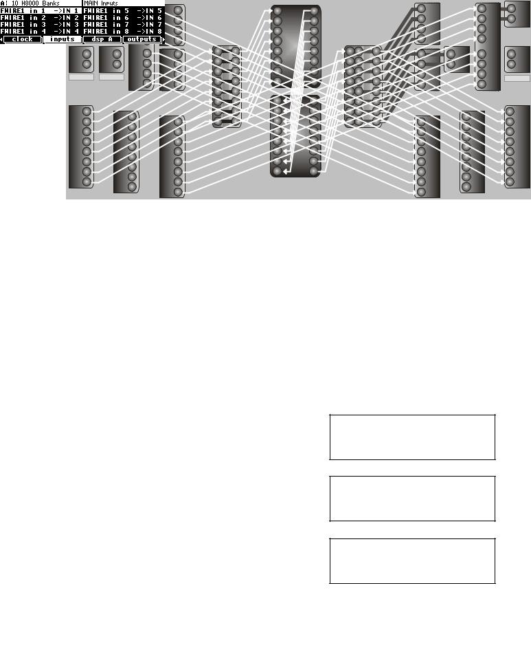
The drawing above has a lot going on and may be a little hard to read, so it might be more helpful to look at the routing screens that produce it.
Here we can see that FireWire1 channels 1 to 8 are connected to MAIN Inputs
DSP A gets its inputs from MAIN Inputs, with the signals renamed to show what is connected to MAIN Inputs, i.e. FireWire 1 to 8.
DSP B gets its inputs from the outputs of DSP
A.
59
3 |
SP/DIF |
|
4 |
coax |
|
|
||
2 SP/DIF |
||
1 |
opto |
|
|
||
1 |
|
|
2 |
out |
|
3 |
||
4 |
FireWire2 |
|
5 |
||
|
||
6 |
|
|
7 |
|
|
8 |
|