

Signal Flow Example
Now that you’re familiar with the actual menu pages employed in signal routing, let’s run through a realistic, but fairly involved signal routing. Four main steps are required for routing any configuration:
Select "sources" for the Main in "input block" at SETUP / inputs.
Select "sources" for DSP A’s inputs at SETUP / dsp A.
Select "sources" for DSP B’s inputs at SETUP / dsp B.
Select "sources" for the Main out "output block" at SETUP / outputs. (Recall that the analog and AES/EBU outputs are always fed from here.)
Optionally:
Select "sources" for the ADAT outputs at SETUP / outputs (third menu page). For the H8000FW:
Select "sources" for AES11/18 outputs at SETUP / outputs (fourth menu page).
Select "sources" for FIREWIRE1 outputs at SETUP / outputs (fifth menu page).
Select "sources" for FIREWIRE2 outputs at SETUP / outputs (sixth menu page).
Once the routing is configured, you can, at your discretion, change levels at:
The analog inputs. Use LEVELS / inputs
Use the "bottom" menu page for pre-A/D adjustments.
Use the "top" menu page for post A/D adjustments (note – using the pre-A/D control will
give a better signal).
The digital inputs.
The inputs to DSP A.
The inputs to DSP B.
The outputs of DSP A.
The outputs of DSP B.
Use LEVELS / inputs.
Use LEVELS / dsp A.
Use LEVELS / dsp B.
Use LEVELS / dsp A.
Use LEVELS / dsp B.
64
|
The analog outputs. |
Use LEVELS / |
output |
. |
|
The digital outputs. |
Use LEVELS / |
|
. |
output |
You can also alter the "Wet/Dry" ratio inside each DSP at LEVELS / dsp A or LEVELS / dsp B.
These levels parameters are discussed at length in Controlling Levels on page 72.
Now, let’s assume we’ve loaded a multichannel effect on DSP B, such as 8*10 Grafic Eq. This program effectively places a 10band equalizer between each of its inputs and outputs. It behaves like eight independent equalizers. Let’s say you want to use these equalizers on a pair of ADAT inputs, a pair of S/P DIF inputs,
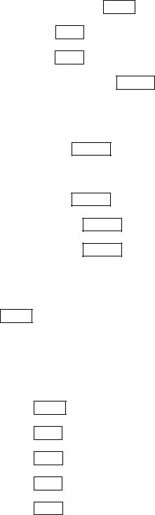
and a pair of AES/EBU inputs. Further, assume you’ve loaded Backward Garden on DSP A and you want to use it to effect a monophonic, pre-amplified guitar that’s being played into stereo cabinets. You also want to record the Backward Garden effect to ADAT channels 7 and 8. Our routing configuration looks like the diagram above. Note that H8000FW extra inputs and outputs are not shown, in the interest of making it remotely readable.
Let’s run through how we’d actually set this up!
Starting with the input block, we need to make sure the S/P DIF inputs are enabled. Do this at the "bottom" inputs menu page in the SETUP area.
Then we need to make sure the appropriate MAIN Inputs are selected. Do this at the "top" inputs menu page in the SETUP area. We’re not planning on using input 2 so it doesn’t really matter what gets assigned there!
Now, we need to assign the ADAT, S/P DIF, and AES/EBU inputs to the first six inputs of DSP B. Do this at the DSP B menu page in the SETUP area (it’s "below" the DSP A menu
65
page!). Strictly speaking, assigning silence (----------- |
) to the last two inputs isn’t really |
necessary since we don’t plan to use those outputs … |
|
Now, we need to assign analog input 1 to DSP A’s inputs 1&2. Do this at the DSP A menu page in the SETUP area. Again, assigning silence to the remaining inputs isn’t necessary because
Backward Garden only has two "live" inputs (its "I/O identifier" is 22).
Cool. Let’s assign the analog outputs now at the outputs menu page in the SETUP area. We want DSP A outputs 1&2 at analog out 1&2 to send to the stereo cabinet. Although we’re not actually
using analog outputs 3&4, we still need to assign DSP B outputs 1&2 to them so that the ADAT outputs can “tap” these signals.
Now let’s assign the AES/EBU outputs at the outputs menu page. The first four AES/EBU outputs are DSP B outputs 3-6. Recall that the S/P DIF outputs simply "tap" AES/EBU
outputs 1/2, in this example, dsp B out 3 and dsp B out 4.
Finally, let’s assign the appropriate signals to the ADAT outputs. Do this at the "bottom" outputs menu page in the SETUP area. Notice that ADAT inputs are also connected to the
ADAT channels that we weren’t interested in using (3 through 6). We probably didn’t need to … H8000FW owners can set up AES11-18 and the FIREWIRE outputs in the same way.
And that’s it! Once you get the hang of it, making custom routing configurations is no sweat! When you are happy with things, don’t forget to save the routing (see next section).
Storing and Loading Routing Configurations
Nevertheless, you don’t have to wrestle with all those parameters every time you want to change the routing configuration. As you’ll recall, in the Overview and Quickstart section we used the Routing Storage area for loading entire routing configurations in one go. In addition to loading the preset routing configurations that came with the H8000FW, you can also save your own configurations for future use.
Block diagrams and descriptions of the preset routing configurations can be found in Loading Routing Configurations on page 25.
66
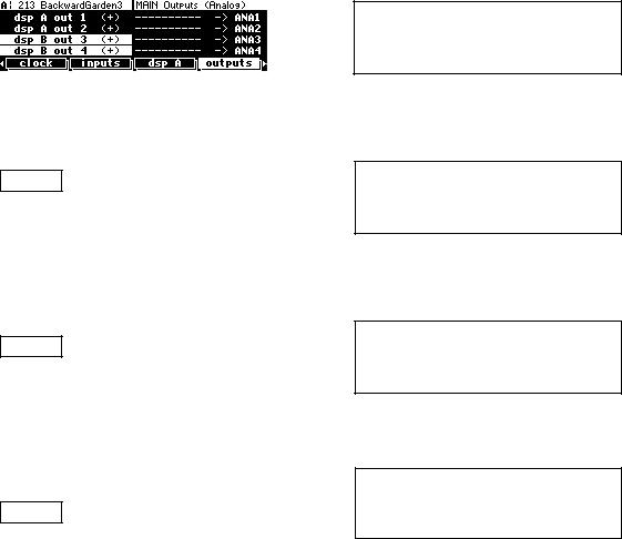
Access the Routing Storage area by holding down the PROGRAM key for one second. The LED next to the PROGRAM key will begin to blink and the upper right-hand portion of the screen will read "Routings." Here we find several SOFT KEYS:
list Lists the routing configurations.
and Jumps between decades or the alphabet depending on the status of
the Sort by parameter in the Criteria menu page.
Criteria Determines the behavior of the list. Will routing configurations be presented numerically or alphabetically? Will you be able to view "factory" configurations? "User" configurations? Configurations on Memory Cards?
Save Saves routing configurations without overwriting original configuration. You have the option to rename the configuration.
update Saves routing configurations to User Memory with a single key press.
remove Deletes the selected routing configurations from User Memory or Card.
These SOFT KEYS behave exactly as they do in the PROGRAM area.
See Loading Programs on page 123, Saving a Program on page 127, and Deleting a Program on page 130 for more details.
To change the one second hold time," see Miscellaneous Setup Options on page 138.
The parameters on the following routing and levels menu pages are saved in the Routing Storage area:
SETUP / dsp A used to assign "sources" for DSP A.
SETUP / dsp B used to assign "sources" for DSP B.
SETUP / inputs used to assign "sources" to the "input block."
SETUP / outputs used to assign "sources" to the outputs.
SETUP / format used to define digital protocols for AES/EBU and S/P DIF
inputs and outputs.
LEVELS / dsp A used to adjust the Wet/Dry mix for DSP A, the output levels
for DSP A, and the input levels for DSP A. 67
LEVELS / dsp B used to adjust the Wet/Dry mix for DSP B, the output levels
for DSP B, and the input levels for DSP B.
Notice that the analog and digital input levels located on the LEVELS / inputs menu page and the analog and digital output levels located on the LEVELS / output menu page, are not saved in the Routing Storage area. This is because these are usually set according to the external signal sources and destination, and not changed according to the preset or routing..
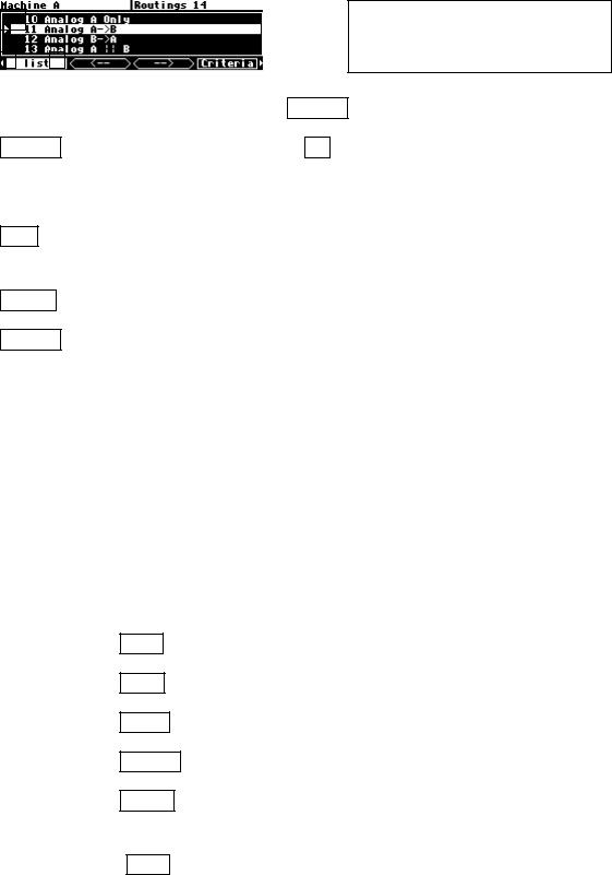
Loading a Routing Remotely Via MIDI
To load a routing remotely, make sure MIDI is enabled, program load is on, and omni mode is off on the midi menu page in the
SETUP area. Routings will load in response to
program change messages on the MIDI channel that corresponds with base channel + 2.
In the example above, base channel is set to 1. So, if we send the program change message "12" on MIDI channel 3 (1 + 2), we would load the routing Analog B->A. You can also load
programs on DSP A using (base channel + 0) and on DSP B using (base channel + 1).
See Loading a Program Remotely on page 123 for more details.
68