


Programs’ Effect on Routing Decisions
As you’ll recall from the Quickstart section, to the right of every program name in the PROGRAM area there are two digits called the "I/O Identifier." On the screen shown to the right:
"Q*10 Grafic Eq" has an "I/O Identifier" of "44" "O*5 Grafic Eq" has an "I/O Identifier" of "88" "Gaspodes Dly_2" has an "I/O Identifier" of "32" "Gaspodes Dly_M" has an "I/O Identifier" of "22"
To understand why the "I/O Identifier" is necessary, we must first understand that, although each DSP has eight inputs and eight outputs, it is not necessarily the case that all of those inputs and outputs will be used by a given program. As has been stated elsewhere in this manual, each program is a unique algorithm. The particulars of a given algorithm dictate how many inputs and outputs will be used, just as they dictate what sorts of parameters are used. For example, a program that acted as a synthesizer would not need any inputs. A program that turned a mono signal into a pseudo-quad signal would only need one input. A program that modulated one stereo signal with another stereo signal would only need two outputs.
So, the "I/O Identifier" tells us at a glance how many inputs and outputs a program uses. The first digit refers to the number of active (live) inputs to the program, and the second digit refers to the number of active (live) outputs to the program. The way these digits correspond to actual inputs and outputs is as you would expect:
0 x |
the program has no inputs. It could be an oscillator or sound effects |
generator. |
|
1 x |
input 1 is live; inputs 2, 3, ..., 8 are dead. |
2 x |
inputs 1 and 2 are live; inputs 3, 4, ..., 8 are dead. |
and so on! |
|
x 0 |
the program has no outputs. Perhaps it's a spectrum analyzer. |
x 1 |
output 1 is live; outputs 2, 3, ..., 8 dead. |
x 2 |
outputs 1 and 2 are live; outputs 3, 4, ..., 8 are dead. |
and so on. |
|
|
69 |
If the I/O Identifier is not visible, this means either that the program has no inputs or outputs (unlikely, except for a small number of information-only presets) or that the program file does not contain I/O Identifier information - this will usually only apply to presets obtained from a DSP4000 or other earlier system.
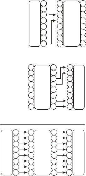
Be mindful of the "I/O Identifiers" when you select your programs and routing configurations. You won’t want to make connections to dead inputs or outputs unless you plan not to use those dead inputs or outputs! You may find yourself frequently ignoring dead inputs or outputs, especially if you load quad or octal routing configurations but only process stereo signals. As long as you don’t fool yourself into thinking the dead inputs or outputs are passing audio, everything is OK! Let’s look at a few examples of routing configurations that rely on connections to dead inputs and outputs and, because of that reliance, fail to do any business.
For example, the setup shown to the right is bad news. The inputs to DSP A will never be heard because the program "VocalVerb 2" doesn’t use DSP inputs 3 and 4! Remember, the first digit in its "I/O Identifier," "2," means that only inputs 1 and 2 are live. Inputs 3 through 8 are dead (they’re shown as dotted circles in the diagram). You won’t hurt the H8000FW by hooking things up this way, but you won’t pass audio!
To the right, we have another bad scene. The program "Big Voice" has an "I/O Identifier" of "22." That means that only DSP outputs 1 and 2 are live. Outputs 3 through 8 are dead, but in the block diagram to the right, it is these dead outputs that are being used. Again, you won’t hurt the H8000FW by hooking things up this way, but you won’t pass audio!
|
1 |
1 |
|
1 |
||
block |
2 |
2 |
running |
2 |
||
4 |
4 |
4 |
||||
|
3 |
|
3 |
DSP A |
3 |
|
Input |
5 |
|
5 |
“Vocal |
5 |
|
6 |
|
6 |
I/O = 28 |
6 |
||
|
|
|
|
|
Verb 2” |
|
|
7 |
|
7 |
|
7 |
|
|
|
|
||||
|
8 |
|
|
8 |
|
8 |
|
|
|
|
|||
1 |
|
1 |
1 |
ANA1 |
2 |
|
2 |
2 |
ANA2 |
3 |
DSP A |
3 |
3 |
ANA3 |
4 |
running |
4 |
4 |
ANA4 |
5 |
“Big |
5 |
5 |
DIG1 |
Voice” |
||||
6 |
I/O = 22 |
6 |
6 |
DIG2 |
7 |
|
7 |
7 |
DIG3 |
8 |
|
8 |
8 |
DIG4 |
Of course, making a connection to a dead input or output is not necessarily a bad thing. You can make "dead connections" as long as you don’t fool yourself into thinking that they’re actually passing signals. For example, you might want to filter a simple stereo signal. You’ll use digital inputs 1 and 2 and digital outputs 1 and 2. You don’t care what’s happening on the rest of the
70
You are actually only using inputs 1/2 and outputs 1/2
|
1 |
1 |
|
1 |
1 |
ANA1 |
block |
2 |
2 |
running |
2 |
2 |
ANA2 |
4 |
4 |
4 |
4 |
ANA4 |
||
|
3 |
3 |
DSP A |
3 |
3 |
ANA3 |
Input |
5 |
5 |
“Stereo |
5 |
5 |
DIG1 |
6 |
6 |
I/O = 22 |
6 |
6 |
DIG2 |
|
|
|
|
Filter” |
|
|
|
|
7 |
7 |
|
7 |
7 |
DIG3 |
|
8 |
8 |
|
8 |
8 |
DIG4 |
digital inputs and outputs. You load the program "Stereo Filter" with an "I/O Identifier" of "22."
For convenience, you load the routing configuration "AES 8 track A only," which makes connections as shown above. Connections are in fact made to the dead inputs 3 through 8 and the dead outputs 3 through 8, but it doesn’t matter in this case. You aren’t attempting to pass signals on these "dead connections" ! You’re only using the live inputs 1 and 2 and the live outputs 1 and 2. Again, making a "dead connection" isn’t a bad thing as long as you don’t fool yourself into thinking that it’s actually passing a signal!
The moral? Not all the inputs and outputs on a given DSP are necessarily live. Exactly how many are live depends on the program that is being run. To prevent signals from becoming "lost," keep the "I/O Identifier" and its impact on your routing configuration in mind!
Before we leave this section, we should mention that, although we just asked you to always keep the "I/O Identifier" in mind, you will seldom need to alter a chosen routing configuration to suit a program in practice. You’ll find that things tend to work out better than the "bad news" examples above might lead you to believe!
71