

Getting Around and Altering Parameters
Adjusting the Brightness and Contrast of the Display
Before we begin to describe the H8000FW’s interface, we ought to make sure you can see the display! To adjust the contrast of the display, press
the SETUP key four times, then press the leftmost SOFT KEY under the display menu. Turn the KNOB to adjust contrast or press the DOWN CURSOR key and turn the KNOB to adjust brightness.
The "Areas" of the H8000FW
The H8000FW’s interface is divided into several functional "areas." You access each area by pressing its key. You’ll know which area you’re in because the LED next to its key illuminates (except for the BYPASS area, but that one’s obvious). The areas are:
PROGRAM Press the PROGRAM key to access this area. Inside you’ll find utilities for sorting programs, loading programs, saving programs, deleting programs, and grouping programs of your choosing into "user
groups." Press the PROGRAM key to access additional SOFT KEYS.
See Program Load, Save, Delete, Etc. on page 115.
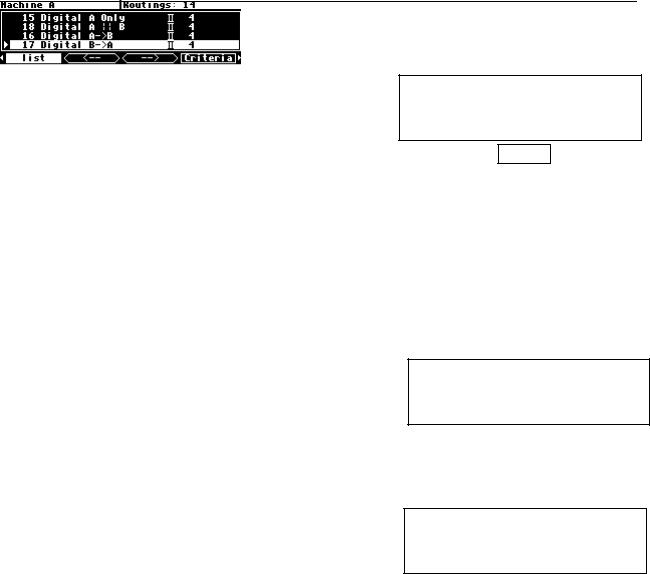
ROUTING Storage Press and hold down the PROGRAM key for one second to access this area. The LED next to the PROGRAM key blinks. Here you’ll find utilities for loading, saving, or deleting "routing configurations."
See Signal Flow Example on page 64.
To change the "hold time," see Miscellaneous Setup Options on page 138.
14
SETUP Storage Press and hold down the PROGRAM key again for one second to access this area. The LED next to the PROGRAM key blinks. Inside you’ll find utilities for loading, saving, or deleting "setup configurations."
See Storing and Loading Setups on page 137.
To change the "hold time," see Miscellaneous Setup Options on page 138.
USERGROUPS Press and hold down the PROGRAM key again for one second to access this area. The LED next to the PROGRAM key blinks. Inside you’ll find utilities for renaming or deleting "User Groups."
See Using User Groups to Organize Useful Programs on page 44.
PARAMETER Press the PARAMETER key to access this area. Here you’ll find the parameters for the currently loaded programs. Continue pressing the PARAMETER key to access additional SOFT KEYS (if available).
See Parameters on page 131.
The PARAMETER key also gives access to the built-in Patch Editor. Press and hold down the PARAMETER key for one second to access this area. The LED next to the PARAMETER key blinks. The Patch Editor
allows you to create your own effects from scratch or to customize programs that already exist.
See the separate Programmer’s Manual for more information on the Patch Editor.
To change the "hold time," see Miscellaneous Setup Options on page 138.
LEVELS Press the LEVELS key to access this area.
Inside you’ll find level and Level Meter parameters.
See Controlling Levels on page 72.
SETUP Press the SETUP key to access this global, "catch-all" area. Inside you’ll find routing parameters, digital setup controls, global MIDI setup, global "external" setup, display contrast/brightness, the pedal
jacks’ setup, dump data utilities, next/previous program advance, and miscellaneous service utilities. Press the SETUP key more than once to access additional SOFT KEYS.
15
Understanding the Display and SOFT KEYS
Every "area" in the H8000FW makes use of the display, so understanding the display is critical. A generic screen of the sort typically found in the PARAMETER area is shown below. It exemplifies various aspects of the display that remain constant no matter what area of the H8000FW you’re in.
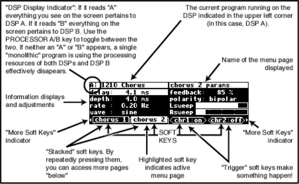
First, in the upper left-hand corner of the screen is either the letter "A," the letter "B," or the beginning of the program name This is the "DSP Display Indicator." If it reads "A," then everything else on a "DSP sensitive" screen is in reference to DSP A. If it reads "B," then everything else on a "DSP sensitive" display is in reference to DSP B. Press the PROCESSOR A/B key to toggle the display between the two DSPs. The screens in the
PROGRAM, PARAMETER, and Patch Editor are "DSP sensitive." Both DSPs are always running, but the display only shows the parameters for one of them at a time. The "DSP Display Indicator" lets you know which one you’re modifying. Look to it often.
If there is no "A" or "B" in the upper left-hand corner of the screen, the H8000FW is running a "monolithic program." Monolithic programs use the signal processing resources of both DSPs. They use the routings for DSP A. While a monolithic program is loaded, DSP B effectively disappears.
The remainder of the upper left-hand corner of the screen always shows the name of the program currently running on the DSP referred to by the "DSP Display Indicator." In
16
the example shown above, we’re running a program "1210 Chorus" on DSP A. The upper right-hand corner of the screen always describes the menu page you’re looking at. In the example shown above, we’re looking at the "chorus 2 params" menu page.
Situated along the bottom of the display are the so-called "SOFT KEYS." The four physical keys located below the display select menu pages or events corresponding to these SOFT KEYS. (They’re called "soft" because their function changes depending on context.) The "More Soft Keys" indicators are the little arrows next to the first and last SOFT KEYS. They indicate that if you press the "area" key you used to access the current display again, you will access more SOFT KEYS. The arrows are meant to imply that more pages exist in a nether-world beyond the display. . .
For example, press the SETUP key to see the "More Soft Keys" indicators.
Press the SETUP key again to get more SOFT
KEYS.
Press the SETUP key a few more times to return to the original set of SOFT KEYS.
A "Stacked" SOFT KEY (shown on the format and pedals menu pages above) indicates that if you repeatedly press the "stacked" SOFT KEY, you will access more menus. The graphic is meant to imply that there are more pages lying "below" the "top" one.
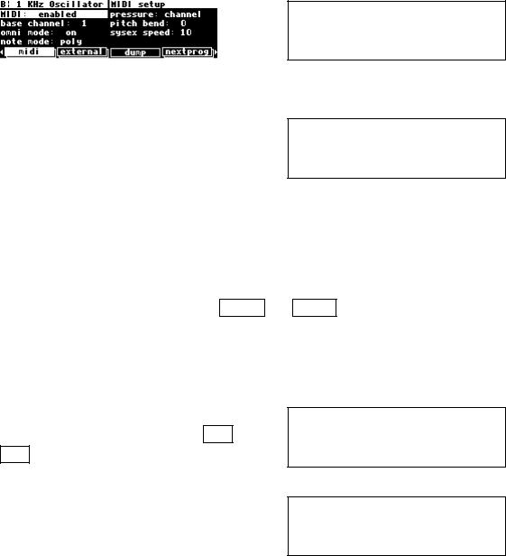
For example, repeatedly press the SETUP key until you see the stacked SOFT KEY midi. Press midi.
Press it again to get a second menu page.
17
Press it again to get a third menu page.
Press it twice more to return to the original menu page.
Pressing a SOFT KEY repeatedly that is not stacked puts the H8000FW into "self-destruct" mode. Just kidding. It has no effect.
When you press a SOFT KEY, it becomes highlighted. The middle section of the screen is a menu page corresponding to that highlighted SOFT KEY. Use the cursor keys to "move around" on the menu page. Use the KNOB, the NUMERIC KEYPAD, and the SELECT key to change and enter values.
See Using the Cursor Keys, the SELECT key, the NUMERIC KEYPAD, and the KNOB on page 19.
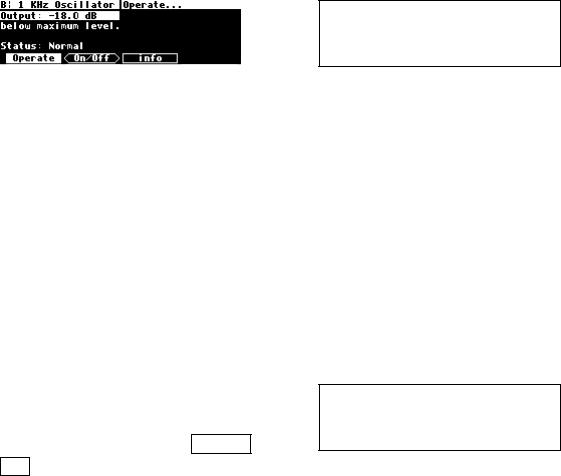
Before moving on, we ought to say that not all SOFT KEYS are menu pages. Some SOFT KEYS are "triggers." A "trigger" is a key that triggers an event, get it? You’ll always know the difference between menu page SOFT KEYS
and trigger SOFT KEYS because menu page SOFT KEYS are rectangular, whereas trigger SOFT KEYS are hexagonal. On this screen Operate and info are menu pages, and <On/Off> is a trigger.
18