

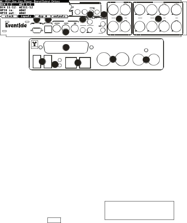
The Back Panel
OPTIONS
a b c |
|
|
WORD CLOCK SP/DIF |
|
|
|
|
|
|
|
|
|
|
|
h |
f |
|
m |
l |
MIDI |
i |
d |
e |
|
|
k |
|
|
|
|
|
o |
|
|
|
|
n |
q |
j |
p |
g |
|
|
||||
|
|
|
|
|
a) AC VOLTAGE SELECTOR
Line up the dot with the triangle so that your preferred voltage is up. It is absolutely essential that you select the voltage corresponding to your local AC power! Check this carefully before first powering the unit, and after moving to a different country.
b)FUSE HOLDER A 1-Amp Slow Blow fuse. Always replace it with the correct value.
c)AC PORT Connect an IEC standard 3-prong AC power cord here. The center post is
chassis ground.
AES/EBU Digital Audio Input/Output (Professional)
Use these connectors to connect professional digital audio gear to the H8000FW. These cables are differential with a shielded twisted pair. Eventide recommends the use of purpose-manufactured Digital Audio cables, which have low capacitance and a controlled impedance to better carry AES signals. Ordinary microphone cables will usually work at 48kHz, but are likely to reduce range and add jitter and possibly distortion to the signal. It is unlikely that long lengths of microphone cable will prove satisfactory for 96kHz operation.
d)
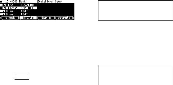
Connect these inputs and outputs to other AES/EBU-specified gear. If the parameter DIN 1/2 on the inputs menu page in the
SETUP area is set to AES/EBU, then digital inputs 1/2 are accepted at AES/EBU input 1/2 jack.
9
Note that AES/EBU 1/2 can be used as sync sources on the H8000 and H8000A, but not on the H8000FW.
See Digital Setup on page 78.
e) ANALOG AUDIO INPUT AND OUTPUT JACKS
The H8000FW’s XLR analog audio output jacks are male. Pin #1 is ground. Pin #2 is +phase (hot) and pin #3 is -phase.
To "unbalance" the jack, use pins #1 and #3 as ground and use pin #2 as "hot." Be aware that this will reduce the maximum output level by 6dB, so you
should usually reduce the output gain by 6dB to compensate. 1
2 
1/4"
See Controlling the Level of the Analog and Digital Outputs on page 76.
3 
If either pins #2 or #3 are unconnected, you will get more noise |
1 |
2 |
than signal !
3
The H8000FW’s analog inputs accept either mono or stereo 1/4" connectors or balanced XLR connectors. The H8000FW’s XLR input connectors are female. Pin #1 is ground. Pin #2 is +phase (hot) and pin #3 is -phase. These may be connected to an unbalanced input as described above.
To "unbalance" the XLR or 1/4" jack, use both pins #1 and #3 as ground and use pin #2 as "hot." If either pins #2 or #3 are unconnected, you will get more noise and hum than signal !
These may be used as both line and guitar inputs, depending on the input level setting. Using a "mono" jack will correctly unbalance the input.
See Controlling the Level of the Analog and Digital Inputs on page 73.
S/P DIF Digital Audio Input/Output (Consumer)
S/P DIF is a consumer digital audio standard, with two audio channels encoded into a single connector. Use these connectors to hook up the H8000FW to CD players, DAT recorders, and other audio gear using this format. The connectors are two-conductor RCA jacks. Your plug should have the shield connected to the sleeve with the single shielded conductor connected at the tip.
10
Eventide recommends the use of professional quality cables made of RG-59/U coaxial cable. Ordinary "hi-fi" type leads will probably prove inadequate. Eventide does not recommend the use of S/PDIF at sample rates above 48kHz.
f) S/P DIF 1/2 INPUT AND OUTPUT JACKS
To enable the S/P DIF digital input 1/2, set DIN 1/2 on the inputs menu page in the SETUP area to S/P DIF. This will disable AES1/2.
Note that these connectors can be used as sync sources on the H8000 and H8000A, but not on the H8000FW.
See Digital Setup on page 78.
g) S/P DIF 3/4 INPUT AND OUTPUT JACKS
To enable the S/P DIF digital input 3/4, set DIN 11/12 on the inputs menu page in the SETUP area to
S/P DIF. This will disable AES11/12. The input
circuitry for S/P DIF 3/4 allows better performance than S/P DIF 1/2 and will operate better at 96kHz or with long leads.
h) FOOT PEDAL JACKS 1 AND 2
Stereo 1/4" connectors. The sleeve is ground reference, the ring is +5 volts (source), and the tip is an analog signal from 0 to 5 volts. Connect either foot switches, foot pedals, or control voltage sources to these inputs to modulate parameters or to trigger events (including remote program loads).
See Foot Pedals 1 and 2 on page 92.
i)RELAY JACK
Two relays are connected to this stereo 1/4" connector. They can be controlled from suitable programs, allowing the H8000FW to drive real-world equipment, and can switch up to 1A at 30V dc. Relay #1 is connected between ring and sleeve, while Relay # 2 is connected between ring and tip. All of these connections are electrically isolated from the H8000FW. See the separate Programming Manual for information on controlling the relays.
j) OPTICAL INPUT AND OUTPUT JACK
These send and receive digital audio to and from other ADAT-capable devices, using a standard "light-pipe" connector. They also support SMUX operation, carrying four channels at 88.2 or 96kHz. To use signals from the ADAT input, select them at the
11
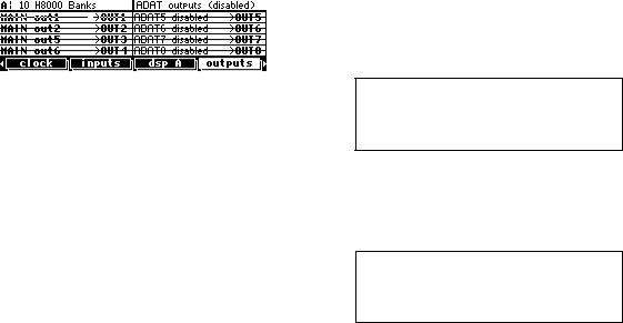
inputs menu page in the SETUP area. To route signals to the ADAT output, select them at the outputs menu page in the SETUP area.
These jacks may also be used as optical-type S/P DIF connectors. The optical input may be assigned to one pair of AES11/18, which will disable that pair as AES inputs. If AES11/12 is
selected as an optical input it cannot also be selected as an electrical S/P DIF input so the DIN11/12 control is disabled.
The optical output may be fed from any one pair from AES11/18. Clearly, if either of these connectors is used for S/P DIF the corresponding ADAT signals will be disabled.
k) MIDI
MIDI is used for instrument-to-instrument digital communications. The H8000FW sends and receives Eventide system exclusive messages that allow a MIDI sequencer or foot pedal (among other things) to remote control the H8000FW. In addition, the H8000FW may respond to standard MIDI messages and may output standard MIDI messages. The H8000FW has three MIDI ports:
IN - the H8000FW accepts (and processes) MIDI messages received at the MIDI In port. The connector is "7 pin" and can also send MIDI messages to a suitably equipped system. A normal "3 pin" MIDI cable can be used as a standard MIDI input.
OUT - the H8000FW sends MIDI messages to other devices via the Out port. MIDI messages are also sent out the serial port if they are "enabled."
THRU - Any MIDI information received at the MIDI In port is echoed directly to the MIDI Thru port regardless of the H8000FW’s configuration (as long as the H8000FW is powered up) .
With the Memory Card removed, the BUSY LED on the front panel illuminates whenever a MIDI message is received at the MIDI In port. Note: If the serial port is "enabled" and MIDI is "enabled," a command received over either the serial port or the MIDI In port causes the port not receiving the command to be ignored until the command is complete.
See MIDI Setup on page 93.
l)EVE/NET
RJ45 jack for use with Eve/Net remote controllers. See the Eventide Web Site http://www.eventide.com for more information on Eve/Net. Do not connect this jack to an Ethernet network or electrical damage may result.
12
m) SERIAL PORT
An IBM PC type RS232 connector that looks like a modem or printer to a connected computer. Connect a "9 pin" serial cable to this port to transfer information to and from a personal computer. Do not use the "null modem" type of cable designed for file transfer between two computers - it will not work.
With the Memory Card removed, the BUSY LED on the front panel illuminates whenever a message is received at the serial port. Note: If the serial port is "enabled" and MIDI is "enabled," a command received over either the serial port or the MIDI In port causes the port not receiving the command to be ignored until the command is complete.
See Setting Up the Serial Port on page 139.
n) FIREWIRE CONNECTORS
Two identical IEEE-1394 FireWire connectors. Typically one is connected to a PC or Mac, and the other is available for “daisy-chain” connections to other FireWire devices or may be left unconnected.
Note: while FireWire is specified as being “hot-swappable”, meaning that connectors may be plugged and un-plugged with power applied, Eventide recommends that this NOT be done, and that where possible FireWire connections be only changed when all equipment is powered down.
o) AES11/18 input and output connector
This DB25 connector carries the input and output signals for AES/EBU signals 11 to 18.
See Connecting AES 11 thru 18 to the H8000FW on page 154.
p) WORD CLOCK INPUT AND OUTPUT JACKS
The H8000FW sends a clock signal from its word clock output which can be used to synchronize other equipment to the H8000FW. The H8000FW can also slave to another device’s word clock output.
q) STATUS LEDS
These two LEDs indicate the status of the FireWire subsystem. The top LED should be lit when a FireWire cable is connected. The lower one should flash from time to time to show activity, especially when a connected device becomes locked or unlocked. If it flashes rapidly and continuously, a bad connected device or connection is indicated.
13