

Cisco. Fundamentals Network Design - Cisco Press
.pdfTopology Database Update Reduction
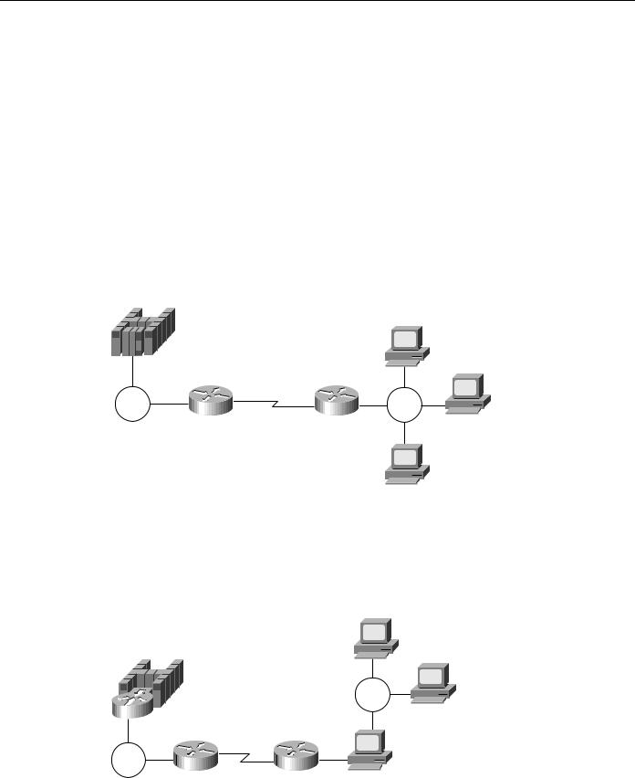
Figure 6-10 Single pair of CP-CP sessions.
|
|
NN3 |
NN1 |
NN2 |
NN4 |
CP-CP sessions
NN5
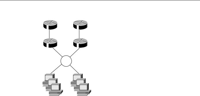
Figure 6-11 shows a more efficient design that also provides redundancy. Every network node has CP-CP sessions with two adjacent network nodes. NN2 has CP-CP sessions with NN3 and NN5. If the link between NN2 and NN3 fails, TDU updates will be sent via NN5 and NN4.
For redundancy purposes, it is recommended that each network node has CP-CP sessions to two other network nodes if possible.
Reducing the Number of Network Nodes
The third technique for reducing the amount of TDU flows in the network is to reduce the number of network nodes by defining APPN nodes only at the edges of the network. Minimizing the number of network nodes also reduces the size of the network topology. The following are some technologies for reducing the number of network nodes:
•
•
•
APPN over DLSw+
APPN over Frame Relay Access Server (FRAS)/BNN or BAN
APPN over RSRB
Figure 6-11 Dual pair of CP-CP sessions.
|
|
NN3 |
NN1 |
NN2 |
NN4 |
NN5
CP-CP sessions
Designing APPN Internetworks 6-15
Scalability Issues
APPN over DLSw+
Data link switching is one way to reduce the number of network nodes in the network. DLSw+ is a means of transporting APPN traffic across a WAN, where APPN network nodes and/or end nodes are defined only at the edges of the network. Intermediate routing is through DLSw+ and not via native SNA.
DLSw+ defines a standard to integrate SNA/APPN and LAN internetworks by encapsulating these protocols within IP. Cisco’s implementation of DLSw, known as DLSw+, is a superset of the current DLSw architecture. DLSw+ has many value-added features that are not available in other vendors’ DLSw implementations. APPN, when used with DLSw, can benefit from the many scalability enhancements that are implemented in DLSw+, such as border peer, on-demand peers, caching algorithms, and explorer firewalls.
In Figure 6-12, sessions between end-node workstations and the host are transported over the DLSw+ network.
Figure 6-12 APPN with DLSw+.
NN
EN
EN
DLSw+ |
DLSw+ |
Token |
Token |
Ring |
Ring |
EN
VTAM acts as the network-node server for remote end-node workstations. Optionally, if multiple VTAMs or data centers exist, APPN on the channel-attached router(s) or on other routers in the data center can offload VTAM by providing the SNA routing capability, as shown in Figure 6-13.
Figure 6-13 APPN with DLSw+ using a channel-attached router.
EN
NN
Token
Ring
EN
Token |
Router |
Router |
|
Ring |
|
||
|
|
|
|
|
DLSw+ |
DLSw+ |
EN |
6-16 Cisco CCIE Fundamentals: Network Design

LOCATE Search Reduction
DLSw+ also brings nondisruptive rerouting in the event of a WAN failure. Using DLSw+ as a transport reduces the number of network nodes in the network. A disadvantage is that remote end-node workstations require WAN connections for NNS services. Another disadvantage is that without APPN in the routers, APPN transmission priority is lost when traffic enters the DLSw+ network.
For detailed information on DLSw and DLSw+, refer to Chapter 7, “Designing DLSw+
Internetworks.”
APPN over FRAS BNN/BAN
If the APPN network is based on a Frame Relay network, one option is to use the FRAS/BNN or the Frame Relay BAN function for host access. Both BNN and BAN allow a Cisco router to attach directly to an FEP. When you use FRAS/BNN, you are assuming that the Frame Relay network is performing the switching and that native routing is not used within the Frame Relay network. For an example of how APPN with FRAS BNN/BAN can be used in your network design, see the section “Example of APPN with FRAS BNN” later in this chapter.
APPN over RSRB
Using RSRB, the SNA traffic can be bridged from a remote site to a data center. The use of RSRB significantly reduces the total number of network nodes in the network, thus reducing the number of TDU flows in the network. Another advantage of using RSRB is that it provides nondisruptive routing in the event of a link failure. For more information on using RSRB, refer to Chapter 4, “Designing SRB Internetworks.”
LOCATE Search Reduction
This section describes the broadcast traffic in an APPN network and how LOCATE searches can become a scalability issue in an APPN network. The impact of LOCATE searches in an APPN network varies from one network to the other. This section first identifies some of the causes of an excessive number of LOCATE searches, and then discusses the following four techniques you can use to minimize them:
•
•
•
•
Safe-Store of Directory Cache
Partial Directory Entries
Central Directory Server (CDS)/Client
Central Resource Registration
An APPN network node provides dynamic location of network resources. Every network node maintains dynamic knowledge of the resources in its own directory database. The distributed directory database contains a list of all the resources in the network. The LOCATE search request allows one network node to search the directory database of all other network nodes in the network.
When an end-node resource requests a session with a target resource that it has no knowledge of, it uses the distributed search capabilities of its network-node server to locate the target resource. If the network node does not have any knowledge of the target resource, the network node forwards the locate search request to all its adjacent network nodes requesting these nodes to assist the network-node server to locate the resource. These adjacent network nodes propagate these locate search requests to their adjacent network nodes. This search process is known as broadcast search.
Designing APPN Internetworks 6-17

Scalability Issues
Although several mechanisms are put into place to reduce the LOCATE broadcast searches (for example, resource registration, and resource caching), there might still be an excessive amount of LOCATE flows in a network for such reasons as the network resources no longer exist, there is a mixture of subarea networks and APPN networks, or the resources are temporarily unavailable.
Safe-Store of Directory Cache
The first technique that you can use to minimize the LOCATE flows in your APPN network is the Safe-Store of Directory Cache, which is supported by the Cisco network-node implementation. Cache entries in a network node’s directory database can be periodically written to a permanent storage medium: a tftp host. This speeds recovery after a network-node outage or initial power loss. Resources do not have to be relearned through a LOCATE broadcast search after a router failure. This reduces spikes of broadcasts that might otherwise occur when the APPN network is restarted.
Partial Directory Entries
The second technique that you can use to minimize the LOCATE flows in your APPN network is to define the resources in the local directory database by identifying the end node or network node where the particular resource is located.
The following is a sample configuration:
appn partner-lu-location CISCO.LU21 owning-cp CISCO.CP2
complete
The preceding example defines the location of an LU named CISCO.LU21 that is located with end node or network node CISCO.CP2. This command improves network performance by allowing directed Locate, instead of a broadcast. The disadvantage is that definitions must be created. To alleviate this definition problem, it may be possible to use partially specified names to define multiple resources.
The following is a sample configuration:
Sample configuration:
appn partner-lu-location CISCO.LU owning-cp CISCO.CP2
wildcard complete
The preceding example defines the location of all the LUs prefixed with the characters LU. Obviously, a naming convention is essential to the success of this type of node definition.
Central Directory Server (CDS)/Client
The third technique that you can use to minimize the LOCATE flows in your APPN network is to use the CDS/client function. The APPN architecture specifies a CDS that allows a designated network node to act as a focal point for locating network resources. In current APPN networks, every network node can potentially perform a broadcast search for a resource. This is because the directory services database is not replicated on every network node.
The CDS function allows a network node, with central directory client support, to send a directed LOCATE search to a CDS. If the CDS has no knowledge of the resource, it performs one broadcast search to find the resource. After the resource is found, the CDS caches the results in its directory. Subsequently, the CDS can provide the location of the resource to other network nodes without performing another broadcast search. The Cisco network-node implementation supports the central directory client function. VTAM is the only product that currently implements the CDS function.
6-18 Cisco CCIE Fundamentals: Network Design

Backup Techniques in an APPN Network
Using the CDS means that there is a maximum of one broadcast search per resource in the network. This significantly reduces the amount of network traffic used for resource broadcast searching. You can define multiple CDSs in an APPN network. A network node learns the existence of a CDS via TDU exchange. If more than one CDS exists, the nearest one is used based on the number of hop counts. If a CDS fails, the route to the nearest alternative CDS is calculated automatically.
Central Resource Registration
The fourth technique that you can use to minimize the LOCATE flows in your APPN network is to use the central resource registration function. An end node registers its local resources at its network-node server. If every resource is registered, all network nodes can query the CDS, which eliminates the need for broadcast searches.
Backup Techniques in an APPN Network
This section provides an overview of the various backup techniques in APPN network. The backup and recovery scenarios are representative of common environments and requirements. The following three backup scenarios are discussed:
•
•
•
A secondary WAN link as a backup to a primary WAN link
Dual WAN links and dual routers providing full redundancy
APPN DLUR backup support using a Cisco CIP router
Link Backup
The first backup technique that you can use in your APPN network is to use a secondary WAN link as a backup to your primary WAN link. By using the concept of auto-activation on demand, you can back up a primary WAN link with a secondary WAN link by using any supported protocols (for example, Point-to-Point [PPP], Switched Multimegabit Data Service [SMDS], and X.25), as shown in Figure 6-14.
Figure 6-14 |
Link backup. |
|||||||
|
|
|
|
|
|
|
|
|
|
|
|
|
|
|
|
|
|
|
|
|
|
|
|
|
|
|
|
|
|
|
|
|
|
|
|
|
|
|
|
|
|
|
|
|
|
|
|
|
|
|
|
|
|
|
|
|
|
|
|
|
|
|
|
|
|
|
|
|
|
|
|
|
|
|
|
|
|
|
|
|
|
|
NNB |
|
|
|
Primary |
|
Secondary |
Frame |
|
|
|
PPP/ISDN |
|
Relay |
|
|
|
link |
|
link |
|
|
|
|
|
|
|
|
NNA
In Figure 6-14, the Frame Relay link is the primary link and the ISDN dial link is the backup link. The requirement is that the ISDN link provides instantaneous backup for the primary link and it remains inactive until the primary link goes down. No manual intervention is needed. To support this, NNA needs to define two parallel transmission groups to NNB.
Designing APPN Internetworks 6-19

Backup Techniques in an APPN Network
The primary link is defined using the following configuration command:
appn link-station PRIMARY port FRAME_RELAY fr-dest-address 35 retry-limit infinite complete
The secondary link is defined as supporting auto-activation using the following configuration command:
appn link-station SECONDARY port PPP
no connect-at-startup adjacent-cp-name NETA.NNB activate-on-demand complete
By specifying no connect-at-startup, the secondary link is not activated upon APPN node startup. To indicate auto-activation support, specify adjacent-cp-name and activate-on-demand.
When the primary link fails, APPN detects the link failure and CP-CP sessions failure, which is disruptive to any existing LU-LU sessions. Because there are multiple links from NNA to NNB, NNA attempts to re-establish the CP-CP sessions over the secondary link. The CP-CP sessions request will activate the secondary dial link automatically.
To ensure that the Frame Relay link is used as primary and the dial PPP link is used as the backup, define the transmission group characteristics to reflect that. For example, use the cost-per-connect-time parameter to define the relative cost of using the dial PPP/ISDN link.
cost-per-connect-time 5
This will make the primary Frame Relay link a lower cost route. Therefore, it is a more desirable route than the secondary dial link because the default cost-per-connect-time is zero. When the primary link becomes active, there is no mechanism in place to automatically switch the sessions back to the primary link. Manual intervention is required.
Full Redundancy
The second backup technique that you can use in your APPN network is dual WAN links and dual routers for full redundancy. In some cases, for example, complete fault tolerance is required for mission-critical applications across the network. You can have dual routers and dual links installed to provide protection against any kind of communications failure.
Figure 6-15 shows how you can use duplicate virtual MAC addresses via RSRB to provide full redundancy and load sharing.
6-20 Cisco CCIE Fundamentals: Network Design
Full Redundancy
Figure 6-15 Full redundancy.
NNA |
|
|
|
NNB |
|
|
|
|
|
NNC |
|
|
|
NND |
|
|
|
|
|
Token |
Ring 100 |
|
Ring |
||
|
The router configuration for NNC is as follows:
source-bridge ring-group 200
!
interface TokenRing0 ring-speed 16 source 100 1 200
!
appn control-point NETA.NNC complete
!
appn port RSRB rsrb
rsrb-virtual-station 4000.1000.2000 50 2 200 complete
The router configuration for NND is as follows:
source-bridge ring-group 300
!
interface TokenRing0 ring-speed 16 source 100 5 300
!
appn control-point NETA.NND complete
!
appn port RSRB rsrb
rsrb-virtual-station 4000.1000.2000 60 3 300 complete
Both NNC and NND define an RSRB port with the same virtual MAC address. Every workstation will define the RSRB virtual MAC address as its destination MAC address of its network-node server. Essentially, a workstation can use either NNC or NND as its network-node server, depending on which node answers the test explorer frame first. The route to NNC consists of the following routing information:
Ring 100 -> Bridge 1 -> Ring 200 -> Bridge 2 -> Ring 50
Route to NND will consist of the following routing information:
Ring 100 -> Bridge 5 -> Ring 300 -> Bridge 3 -> Ring 60
Designing APPN Internetworks 6-21
APPN in a Multiprotocol Environment
When NND fails, sessions on NND can be re-established over NNC instantaneously. This is analogous to the duplicate Token Ring interface coupler (TIC) support on the FEP except that no hardware is required. In Cisco’s RSRB implementation, as shown in Figure 6-15, Segment 20 and Bridge 1, and Segment 30 and Bridge 2 are virtual. Duplicate MAC address can be supported without the hardware in place.
SSCP Takeover
The third backup technique is to use APPN DLUR with a Cisco CIP router to support transfer of resource ownership from one System Services Control Point (SSCP) (VTAM) to another when a failure occurs. This includes maintaining existing sessions over the failure. DLUS/DLUR can provide the capability to transfer SSCP ownership from the primary SSCP to the backup SSCP. It then examines how DLUR can provide the capability to obtain SSCP services from the backup SSCP without terminating LU-LU sessions that are in progress.
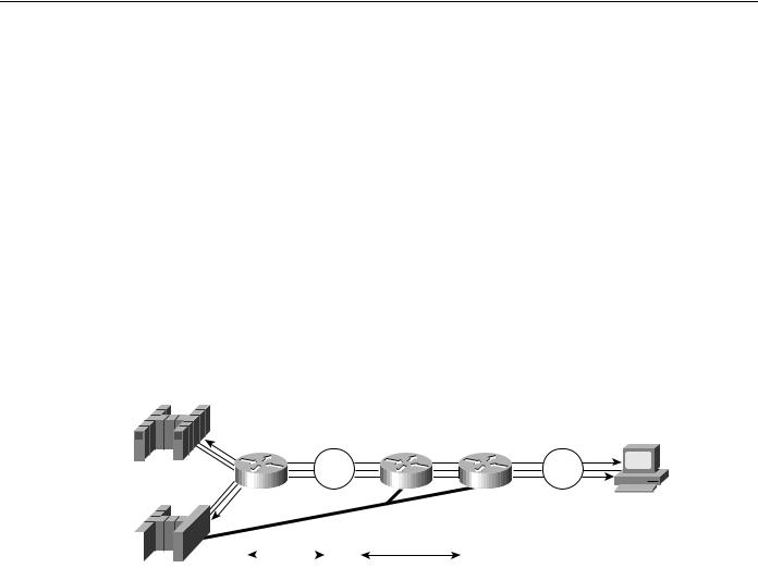
Figure 6-16 illustrates how the FEP can be replaced with a CIP router running CIP SNA (CSNA).
Figure 6-16 SSCP takeover with APPN and CIP.
VTAMA/DLUS
CIP CSNA |
NNB |
NNA DLUR |
Token |
|
Token |
Ring |
|
Ring |
VTAMB
LUA
|
|
|
|
|
|
|
|
|
|
|
|
|
|
|
|
|
|
|
|
|
|
|
|
|
|
|
|
|
|
|
|
|
|
|
|
|
|
|
|
|
|
|
|
|
|
|
|
|
|
|
|
|
|
|
|
|
|
|
|
|
|
|
|
|
|
|
|
|
|
|
|
|
|
|
Backup DLUS |
LU-LU session |
SSCP-PU/LU sessions |
DLUS-DLUR LU6.2 pipe |
|||||||||||
In this example, VTAMA is the primary DLUS, VTAMB is the backup DLUS, and CIP router is configured as the DLUR. Assume that LUA requests to log on to an application that is residing on VTAMB. When VTAMA and the DLUS to DLUR connections fail, the DLUR node attempts to establish a session with VTAMB, which is configured as backup DLUS. When the control sessions to the DLUS are active, the DLUR node notifies VTAMB about all the active downstream physical and logical units. VTAMB sends active physical unit (ACTPU) and active logical unit (ACTLU) commands to these downstream devices. This transfers the resource ownership from VTAMA to VTAMB.
After the SSCP-PU and SSCP-LU sessions are re-established with VTAMB, new LU-LU sessions are possible. In addition, the DLUR node notifies VTAMB about all the dependent logical units that have active sessions.
The LU-LU path between VTAMB and LUA would be VTAMB -> NNB -> NNA -> LUA. When VTAMA fails, LU-LU sessions are not disrupted because VTAMA is not part of the LU-LU session path. In fact, LUA has no knowledge that the owning SSCP (VTAMA) failed and a new SSCP became the new owner. This process is transparent to LUA.
APPN in a Multiprotocol Environment
The trend in internetworking is to provide network designers with greater flexibility in building multiprotocol networks. Cisco provides the following two mechanisms to transport SNA traffic over an internetwork:
6-22 Cisco CCIE Fundamentals: Network Design

Bandwidth Management and Queuing
•
•
Encapsulation
Natively via APPN
The key to building multiprotocol internetworks is to implement some kind of traffic priority or bandwidth reservation to ensure acceptable response time for mission-critical traffic while maintaining some internetworking resource for less delay-sensitive traffic.
Bandwidth Management and Queuing
The following are some Cisco bandwidth management and queuing features that can enhance the overall performance of your network:
•
•
•
•
Priority queuing
Custom queuing
Weighted fair queuing
APPN buffer and memory management
For many years, the mainframe has been the dominant environment for processing business-critical applications. Increasingly powerful intelligent workstations, the creation of client-server computing environments, and higher bandwidth applications are changing network topologies. With the proliferation of LAN-based client-server applications, many corporate networks are migrating from purely hierarchical SNA-based networks to all-purpose multiprotocol internetworks that can accommodate the rapidly changing network requirements. This is not an easy transition. Network designers must understand how well the different protocols use shared network resources without causing excessive contentions among them.
Cisco has for many years provided technologies that encapsulate SNA traffic and allow consolidation of SNA with multiprotocol networks. APPN on the Cisco router provides an additional option in multiprotocol internetworks where SNA traffic can now flow natively and concurrently with other protocols. Regardless of the technology used in a multiprotocol environment, network performance is the key consideration.
Some of the major factors affecting network performance in a multiprotocol environment are as follows:
•Media access speed—The time it takes for a frame to be sent over a link. The capacity requirement of the network must be understood. Insufficient network capacity is the primary contributor to poor performance. Whether you have a single protocol network or a multiprotocol network, sufficient bandwidth is required.
•Congestion control—The router must have sufficient buffering capacity to handle instantaneous bursts of data. In order to support a multiprotocol environment, buffer management plays an important role to ensure that one protocol does not monopolize the buffer memory.
•Latency in the intermediate routers—This includes packet processing time while traversing a router and queuing delay. The former constitutes a minor part of the total delay. The latter is the major factor because client-server traffic is bursty.
Typically, subarea SNA traffic is highly predictable and has low bandwidth requirements. Compared to SNA traffic, client-server traffic tends to be bursty in nature and has high bandwidth requirements. Unless there is a mechanism in place to protect mission-critical SNA traffic, network performance could be impacted.
Designing APPN Internetworks 6-23
APPN in a Multiprotocol Environment
Cisco provides many internetworking solutions to enterprise networks by allowing the two types of traffic with different characteristics to coexist and share bandwidth; at the same time providing protection for mission-critical SNA data against less delay-sensitive client-server data. This is achieved through the use of several priority queuing and/or bandwidth reservation mechanisms.
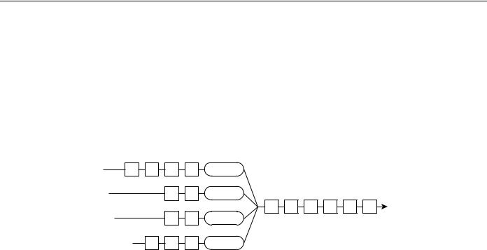
For example, interface priority output queuing provides a way to prioritize packets transmitted on a per interface basis. The four possible queues associated with priority queuing—high, medium, normal and low—are shown in Figure 6-17. Priorities can be established based upon the protocol type, particular interface, SDLC address, and so forth.
Figure 6-17 Four queues of priority queuing.
SNA |
S |
S |
S |
S |
High |
|
|
traffic |
|
|
|||||
|
|
|
|
|
|
|
|
TCP/IP |
|
|
T |
T |
Medium |
|
|
traffic |
|
|
|
|
|||
|
|
|
|
T |
T |
S S S S |
|
NetBIOS |
|
|
|
|
|||
|
|
N |
N |
Normal |
|
|
|
traffic |
|
|
|
|
|||
|
|
|
|
|
|
|
|
Miscellaneous |
M |
M |
M |
Low |
|
|
|
traffic |
|
|
|
||||
|
|
|
|
|
|
|
|
In Figure 6-18, SNA, TCP/IP, NetBIOS and other miscellaneous traffic are sharing the media. The SNA traffic is prioritized ahead of all other traffic, followed by TCP/IP, and then NetBIOS, and finally other miscellaneous traffic. There is no aging algorithm associated with this type of queuing. Packets that are queued to the high priority queue are always serviced prior to the medium queue, the medium queue is always serviced before the normal queue, and so forth.
Priority queuing, however, introduces a fairness problem in that packets classified to lower priority queues might not get serviced in a timely manner, or at all. Custom queuing is designed to address this problem. Custom queuing allows more granularity than priority queuing. In fact, this feature is commonly used in the internetworking environment in which multiple higher-layer protocols are supported. Custom queuing reserves bandwidth for a specific protocol, thus allowing mission-critical traffic to receive a guaranteed minimum amount of bandwidth at any time.
The intent is to reserve bandwidth for a particular type of traffic. For example, in Figure 6-18, SNA has 40 percent of the bandwidth reserved using custom queuing, TCP/IP 20 percent, NetBIOS
20 percent, and the remaining protocols 20 percent. The APPN protocol itself has the concept of COS that determines the transmission priority for every message. APPN prioritizes the traffic before sending it to the DLC transmission queue.
6-24 Cisco CCIE Fundamentals: Network Design