

Cisco. Fundamentals Network Design - Cisco Press
.pdfSummary
Figure 6-34 APPN network with FRAS BNN.
|
VTAM NN/CDS |
|
|
EN or LEN |
||||||||||||||||||
|
|
|
|
|
|
|
|
|
|
|
|
|
|
|
|
|
|
|
|
|
|
Company A |
|
|
|
|
|
|
|
|
|
|
|
|
|
|
|
|
|
|
|
|
|
|
|
|
|
|
|
|
|
|
|
|
|
|
|
|||||||||||
|
|
|
|
|
|
|
|
|
|
|
|
|||||||||||
IBM |
|
|
|
|
|
|
|
|
|
|
|
|
|
|
|
|
|
|
|
|
|
Company B |
|
|
|
|
|
|
|
|
|
|
|
|
|
|
|
|
|
|
|
|
|
Company C |
|
|
|
|
|
|
|
|
|
|
|
|||||||||||||
|
|
|
|
|
|
|
|
|
|
|
|
|
|
|
|
|
|
|
|
|
|
|
|
|
|
|
|
|
|
|
|
|
|
|
|
|
|
|
|
|
|
|
|
|
|
|
|
|
|
|
|
|
|
|
|
|
|
|
|
|
|
|
|
|
|
|
|
|
|
|
FDDI |
|
NN1 |
Router |
Router |
NN2 |
LU-LU session |
|
Frame |
|
|
|
Relay |
|
CP-CP session |
|
|
|
FRAS BNN |
Router |
Router |
FRAS BNN |
|
Token |
Token |
|
|
Ring |
Ring |
|
EN |
|
|
EN |
Implementing FRAS BNN rather than a full APPN network node on the access routers directly reduces the number of network nodes. This allows the network to scale without the concern of TDU flows. This is proven to be a viable solution for this company for the time being because LAN-to-LAN connectivity is not an immediate requirement. The remote routers can be migrated to support APPN border node when it becomes available.
In this environment, CP-CP sessions are supported over the Frame Relay network. The central directory server and the concept of Connection Network are fully supported. LU-LU sessions can be set up using the direct route without traversing VTAM, as shown in Figure 6-34. The only function that is lost with FRAS BNN is COS for traffic traveling from the remote FRAS BNN router to the data center.
Summary
Recall that this chapter discussed developing the network design and planning a successful migration to APPN. It covered the following topics:
•
•
•
•
Evolution of SNA
When to Use APPN as Part of a Network Design
When to Use APPN Versus Alternative Methods of SNA Transport
Overview of APPN
Designing APPN Internetworks 6-55

Summary
•Scalability Issues
•Backup Techniques in an APPN Network
•APPN in a Multiprotocol Environment
•Network Management
•Configuration Examples
6-56 Cisco CCIE Fundamentals: Network Design

C H A P T E R 7
Designing DLSw+ Internetworks
This chapter contains the following information:
•
•
•
Introduction to DLSw+
Getting Started with DLSw+
DLSw+ Advanced Features
Introduction to DLSw+
This section describes Data Link Switching Plus (DLSw+) and provides configuration examples to enable you to quickly design and configure simple DLSw+ networks. It reviews the key components of the data-link switching (DLSw+) features and describes the extensions to the standard that are included in DLSw+. This section also describes advanced features, tells when to use them, and includes examples of how to use these features. It provides tuning, hierarchical design, meshed design, debug, and migration guidance. Finally, it recommends how to proceed with designing your network. This section can be used as a reference only (for configuration examples), as a tuning guide, or as a guide to design a complete DLSw+ network.
DLSw+ Defined
DLSw+ is a means of transporting Systems Network Architecture (SNA) and NetBIOS traffic over a campus or wide-area network (WAN). The end systems can attach to the network over Token Ring, Ethernet, Synchronous Data Link Control (SDLC) protocol, Qualified Logical Link Control (QLLC), or Fiber Distributed Data Interface (FDDI). (FDDI is supported on the Cisco 7000 series only and requires Cisco IOS Release11.2 or later.) DLSw+ switches between diverse media and locally terminates the data links, keeping acknowledgments, keepalives, and polling off the WAN. Local termination of data links also eliminates data-link control timeouts that can occur during transient network congestion or when rerouting around failed links. Finally, DLSw+ provides a mechanism for dynamically searching a network for SNA or NetBIOS resources and includes caching algorithms that minimize broadcast traffic.
In this document, DLSw+ routers are referred to as peer routers, peers, or partners. The connection between two DLSw+ routers is referred to as a peer connection. A DLSw+ circuit compromises the data-link control connection between the originating end system and the originating router, the connection between the two routers (typically a Transport Control Protocol [TCP] connection), and the data-link control connection between the target router and the target end system. A single peer connection can carry multiple circuits.
Designing DLSw+ Internetworks 7-1

Introduction to DLSw+
DLSw+ supports circuits between SNA physical units (PUs) or between NetBIOS clients and servers. The SNA PU connectivity supported is PU 2.0/2.1-to-PU 4 (attached via any supported data-link controls), PU 1-to-PU 4 (SDLC only), PU 4-to-PU 4 (Token Ring only), and PU 2.1-to- PU 2.1 (any supported data-link control). See Appendix B, “IBM Serial Link Implementation Notes,” for details about DLSw+ connectivity.
Note N PU 4-to-PU 4 connectivity supports only a single path between front-end processors (FEPs) because of an idiosyncrasy in how FEPs treat duplicate source-route bridged paths. In addition, remote load is not supported.
DLSw Standard
The DLSw standard was defined at the Advanced Peer-to-Peer Networking (APPN) Implementers Workshop (AIW) in the DLSw-related interest group. The current standard is Version 1, which is documented in RFC 1795. RFC 1795 makes obsolete RFC 1434, which described IBM’s original 6611 implementation of DLSw.
The DLSw standard describes the Switch-to-Switch Protocol (SSP) used between routers (called data-link switches) to establish DLSw peer connections, locate resources, forward data, handle flow control, and perform error recovery. RFC 1795 requires that data-link connections are terminated at the peer routers, that is, the data-link connections are locally acknowledged and, in the case of Token Ring, the routing information field (RIF) ends at a virtual ring in the peering router.
By locally terminating data-link control connections, the DLSw standard eliminates the requirement for link-layer acknowledgments and keepalive messages to flow across the WAN. In addition, because link-layer frames are acknowledged locally, link-layer timeouts should not occur. It is the responsibility of the DLSw routers to multiplex the traffic of multiple data-link controls to the appropriate TCP pipe and to transport the data reliably across an IP backbone. Before any endsystem communication can occur over DLSw, the following must take place:
•
•
•
Establish peer connections
Exchange capabilities
Establish circuit
Establish Peer Connections
Before two routers can switch SNA or NetBIOS traffic, they must establish two TCP connections between them. The standard allows one of these TCP connections to be dropped if it is not required. (Cisco routers will drop the extra TCP connection unless they are communicating with another vendor’s router that requires two TCP connections.) The standard also allows additional TCP connections to be made to allow for different levels of priority.
Exchange Capabilities
After the TCP connections are established, the routers exchange their capabilities. Capabilities include the DLSw version number, initial pacing windows (receive window size), NetBIOS support, list of supported link service access points (SAPs), and the number of TCP sessions supported. Media Access Control (MAC) address lists and NetBIOS name lists can also be exchanged at this time, and if desired, a DLSw partner can specify that it does not want to receive certain types of search frames. It is possible to configure the MAC addresses and NetBIOS names of all resources that will use DLSw and thereby avoid any broadcasts. After the capabilities exchange, the DLSw partners are ready to establish circuits between SNA or NetBIOS end systems.
7-2 Cisco CCIE Fundamentals: Network Design

DLSw Standard
Establish Circuit
Circuit establishment between a pair of end systems includes locating the target resource (based on its destination MAC address or NetBIOS name) and setting up data-link control connections between each end system and its data-link switch (local router). SNA and NetBIOS are handled differently. SNA devices on a LAN find other SNA devices by sending an explorer frame (a TEST or an exchange identification [XID] frame) with the MAC address of the target SNA device. When a DLSw router receives an explorer frame, the router sends a canureach frame to each of the DLSw partners. If one of its DLSw partners can reach the specified MAC address, the partner replies with an icanreach frame. The specific sequence includes a canureach ex (explorer) to find the resource and a canureach cs (circuit setup) that triggers the peering routers to establish a circuit.
At this point, the DLSw partners establish a circuit that consists of three connections: the two data-link control connections between each router and the locally attached SNA end system, and the TCP connection between the DLSw partners. This circuit is uniquely identified by the source and destination circuit IDs, which are carried in all steady state data frames in lieu of data-link control addresses such as MAC addresses. Each circuit ID is defined by the destination and source MAC addresses, destination and source link service access points (LSAPs), and a data-link control port ID. The circuit concept simplifies management and is important in error processing and cleanup. Once the circuit is established, information frames can flow over the circuit.
NetBIOS circuit establishment is similar, but instead of forwarding a canureach frame that specifies a MAC address, DLSw routers send a name query (NetBIOS NAME-QUERY) frame that specifies a NetBIOS name. Instead of an icanreach frame, there is a name recognized (NetBIOS NAME-RECOGNIZED) frame.
Most DLSw implementations cache information learned as part of the explorer processing so that subsequent searches for the same resource do not result in the sending of additional explorer frames.
Flow Control
The DLSw standard describes adaptive pacing between DLSw routers but does not indicate how to map this to the native data-link control flow control on the edges. The DLSw standard specifies flow control on a per-circuit basis and calls for two independent, unidirectional circuit flow-control mechanisms. Flow control is handled by a windowing mechanism that can dynamically adapt to buffer availability, TCP transmit queue depth, and end-station flow-control mechanisms. Windows can be incremented, decremented, halved, or reset to zero.
The granted units (the number of units that the sender has permission to send) are incremented with a flow-control indication from the receiver (similar to classic SNA session-level pacing). Flow-control indicators can be one of the following types:
•Repeat¾Increment granted units by the current window size
•Increment¾Increment the window size by one and increment granted units by the new window size
•Decrement¾Decrement window size by one and increment granted units by the new window size
•Reset¾Decrease window to zero and set granted units to zero to stop all transmission in one direction until an increment flow-control indicator is sent
•Half¾Cut the current window size in half and increment granted units by the new window size
Flow-control indicators and flow-control acknowledgments can be piggybacked on information frames or can be sent as independent flow-control messages, but reset indicators are always sent as independent messages.
Designing DLSw+ Internetworks 7-3

Introduction to DLSw+
DLSw+ Features
DLSw+ is Cisco’s implementation of DLSw. It goes beyond the standard to include the advanced features of Cisco’s current remote source-route bridging (RSRB) and provides additional functionality to increase the overall scalability of DLSw. DLSw+ includes enhancements in the following areas:
•Scalability¾Constructs IBM internetworks in a way that reduces the amount of broadcast traffic and therefore enhances their scalability
•Availability¾Dynamically finds alternative paths quickly, and optionally load-balances across multiple active peers, ports, and channel gateways
•Transport flexibility ¾Higher-performance transport options when there is enough bandwidth to handle the traffic load without risk of timeouts, and the option to use lower-overhead solutions when bandwidth is at a premium and nondisruptive rerouting is not required
•Modes of operation¾Dynamically detects the capabilities of the peer router, and operates according to those capabilities
DLSw+ Improved Scalability
One of the most significant factors that limits the size of LAN internetworks is the amount of explorer traffic that traverses the WAN. There are several optimizations in DLSw+ to reduce the number of explorers.
Peer Group Concept
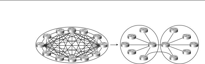
Perhaps the most significant optimization in DLSw+ is a feature known as peer groups. Peer groups are designed to address the broadcast replication that occurs in a fully meshed network. When any-to-any communication is required (for example, for NetBIOS or APPN environments), RSRB or standard DLSw implementations require peer connections between every pair of routers.
This setup is not only difficult to configure, it results in branch access routers having to replicate search requests for each peer connection. This wastes bandwidth and router cycles. A better concept is to group routers into clusters and designate a focal router to be responsible for broadcast replication. This capability is included in DLSw+.
With DLSw+, a cluster of routers in a region or a division of a company can be combined into a peer group. Within a peer group, one or more of the routers are designated to be the border peers. Instead of all routers peering to one another, each router within a group peers to the border peer; border peers establish peer connections with each other (see Figure 7-1). When a DLSw+ router receives a TEST frame or NetBIOS NAME-QUERY, it sends a single explorer frame to its border peer. The border peer forwards the explorer on behalf of the peer group member. This setup eliminates duplicate explorers on the access links and minimizes the processing required in access routers.
7-4 Cisco CCIE Fundamentals: Network Design
DLSw+ Features
Figure 7-1 The peer group concept can be used to simplify and scale any-to-any networks.
Once the correct destination router is found, an end-to-end peer connection (TCP or IP) is established to carry end-system traffic. This connection remains active as long as there is end-system traffic on it, and it is dynamically torn down when not in use, permitting casual, any-to-any communication without the burden of specifying peer connections in advance. It also allows any-to-any routing in large internetworks in which persistent TCP connections between every pair of routers would not be possible.
Explorer Firewalls
To further reduce the amount of explorer traffic that enters the WAN, there are a number of filter and firewall techniques to terminate the explorer traffic at the DLSw+ router. A key feature is the explorer firewall.
An explorer firewall permits only a single explorer for a particular destination MAC address to be sent across the WAN. While an explorer is outstanding and awaiting a response from the destination, subsequent explorers for that MAC address are not propagated. After the explorer response is received at the originating DLSw+, all subsequent explorers receive an immediate local response. This eliminates the start-of-day explorer storm that many networks experience.
DLSw+ Enhanced Availability
One way DLSw+ offers enhanced availability is by maintaining a reachability cache of multiple paths for local and remote destination MAC addresses or NetBIOS names. For remote resources, the path specifies the peer to use to reach this resource. For local resources, the path specifies a port number. If there are multiple paths to reach a resource, the router will mark one path preferred and all other paths capable. If the preferred path is not available, the next available path is promoted to the new preferred path, and recovery over an alternative path is initiated immediately. The way that multiple capable paths are handled with DLSw+ can be biased to meet the needs of the network:
•Fault tolerance¾Biases circuit establishment over a preferred path, but also rapidly reconnects on an active alternative path if the preferred path is lost
•Load balancing¾Distributes circuit establishment over multiple DLSw+ peers in the network or ports on the router
The default for DLSw+ is to use fault-tolerant mode. In this mode, when a DLSw+ peer receives a TEST frame for a remote resource, it checks its cache. If it finds an entry and the entry is fresh (that is, if it is not verified within the last verify interval), the DLSw+ peer responds immediately to the test frame and does not send a canureach frame across the network. If the cache entry is stale, the originating DLSw+ peer sends a canureach directly to each peer in the cache to validate the cache entries (this is known as a directed verify). If any peer does not respond, it is deleted from the list. This may result in reordering the cache. The SNA-VERIFY-INTERVAL is configurable and is the
Designing DLSw+ Internetworks 7-5
Introduction to DLSw+
length of time a router waits before marking the cache entry stale. The SNA-CACHE-TIMEOUT is the interval that cache entries are maintained before they are deleted. It defaults to 16 minutes and is configurable.
At the destination DLSw+ router, a slightly different procedure is followed using the local cache entries. If the cache entry is fresh, the response is sent immediately. If the cache entry is stale, a single route broadcast test frame is sent over all the ports in the cache. If a positive response is received, an icanreach frame is sent to the originating router. Test frames are sent every 30 seconds (SNA-RETRY-INTERVAL) for a three-minute period (SNA-EXPLORER-TIMEOUT). These timers are configurable.
Alternatively, when there are duplicate paths to the destination end system, you can configure load balancing, which causes DLSw+ to alternate new circuit requests in a round-robin fashion through the list of capable peers or ports.
This feature is especially attractive in SNA networks. A very common practice used in the hierarchical SNA environment is assigning the same MAC address to different mainframe channel gateways¾for example, FEPs or Cisco routers with Channel Interface Processors (CIPs). If one channel gateway is unavailable, alternative channel gateways are dynamically located without any operator intervention. Duplicate MAC addressing also allows load balancing across multiple active channel gateways or Token Ring adapters.
DLSw+ ensures that duplicate MAC addresses are found, and it caches up to four DLSw peers or interface ports that can be used to find the MAC address. This technique can be used for fault tolerance and load balancing. When using this technique for fault tolerance, it facilitates a timely reconnection after circuit outages. When using this technique for load balancing, it improves overall SNA performance by spreading traffic across multiple active routers, Token Ring or FDDI adapters, or channel gateways, as shown in Figure 7-2. Load balancing not only enhances performance, it also speeds up recovery from the loss of any component in a path through the network because a smaller portion of the network is affected by the loss of any single component.
Figure 7-2 DLSw+ caching techniques provide load balancing across multiple central site routers, Token Rings, and channel gateways.
Mac 1 Peer C |
Peer B |
T1C1 Port 1 |
|
|
Port 2 |
||
|
|
||
Peer B |
|
|
Port 3 |
Any DLC |
|
|
Peer C |
Peer A |
|
|
|
|
|
Token |
TokenToken |
|
|
Ring |
RingRing |
In addition to supporting multiple active peers, DLSw+ supports backup peers, which are only connected when the primary peer is unreachable.
7-6 Cisco CCIE Fundamentals: Network Design

DLSw+ Features
DLSw+ Transport Flexibility
The transport connection between DLSw+ routers can vary according to the needs of the network and is not tied to TCP/IP as the DLSw standard is. Cisco supports four transport protocols between DLSw+ routers:
•TCP/IP¾Transports SNA and NetBIOS traffic across WANs when local acknowledgment is required to minimize unnecessary traffic and prevent data-link control timeouts and when nondisruptive rerouting around link failures is critical; this transport option is required when DLSw+ is operating in DLSw standard mode.
•FST/IP¾Transports SNA and NetBIOS traffic across WANs with an arbitrary topology; this solution allows rerouting around link failures, but recovery may be disruptive depending on the time required to find an alternative path; this option does not support local acknowledgment of frames.
•Direct¾Transports SNA and NetBIOS traffic across a point-to-point or Frame Relay connection when the benefits of an arbitrary topology are not important and when nondisruptive rerouting around link failures is not required; this option does not support local acknowledgment of frames.
•DLSw Lite¾Transports SNA and NetBIOS traffic across a point-to-point connection (currently only Frame Relay is supported) when local acknowledgment and reliable transport are important, but when nondisruptive rerouting around link failures is not required; DLSw Lite uses RFC 1490 encapsulation of Logical Link Control type 2 (LLC2).
DLSw+ Modes of Operation
Cisco has been shipping IBM internetworking products for many years. There is a substantial installed base of Cisco routers running RSRB today. Therefore, it is essential for DLSw+ and RSRB to coexist in the same network and in the same router. In addition, because DLSw+ is based on the new DLSw standard, it must also interoperate with other vendors’ implementations that are based on that DLSw standard.
There are three modes of operation for DLSw+:
•Dual mode¾A Cisco router can communicate with some remote peers using RSRB and with others using DLSw+, providing a smooth migration path from RSRB to DLSw+. In dual mode, RSRB and DLSw+ coexist on the same box; the local peer must be configured for both RSRB and DLSw+; and the remote peers must be configured for either RSRB or DLSw, but not both.
•Standards compliance mode¾DLSw+ can detect automatically (via the DLSw capabilities exchange) if the participating router is manufactured by another vendor, therefore operating in DLSw standard mode.
•Enhanced mode¾DLSw+ can detect automatically that the participating router is another DLSw+ router, therefore operating in enhanced mode, making all the features of DLSw+ available to the SNA and NetBIOS end systems.
Some of the enhanced DLSw+ features are also available when a Cisco router is operating in standardscompliance mode with another vendor’s router. In particular, enhancements that are locally controlled options on a router can be accessed even though the remote router does not have DLSw+. These enhancements include load balancing, local learning (the capability to determine whether a destination is on a LAN before sending canureach frames across a WAN), explorer firewalls, and media conversion.
Designing DLSw+ Internetworks 7-7

Getting Started with DLSw+
How to Proceed
If you have a simple hierarchical network with a small volume of SNA traffic, read the “Getting Started with DLSw+” section, which describes what configuration commands are required in all DLSw+ implementations and provides configuration examples for SDLC, Token Ring, Ethernet, and QLLC. After reading the “Getting Started with DLSw+” section, you can read about advanced features, customization, and bandwidth management.
This chapter describes how to use DLSw+ in conjunction with downstream physical unit (DSPU) concentration, LAN Network Manager, APPN, and native client interface architecture (NCIA).
Getting Started with DLSw+
This section describes the basic configuration commands required for a DLSw+ network. It begins with a description of the minimum required configuration and then provides examples for Token Ring, Ethernet, SDLC, and QLLC environments. If you are unfamiliar with router configuration, you should also review the examples in Appendix A, “Subnetting an IP Address Space.” These examples illustrate how to configure not only routers, but also the attaching end systems. They show how to configure canonical addresses, static routes, and loopback addresses.
Minimum Required Configuration
Configuring DLSw+ on most networks is not difficult. Every router that supports DLSw+ must have a dlsw local-peer command; dlsw remote-peer commands are optional, but usually at least one side of a peer connection must configure a remote peer. If a DLSw+ peer configuration omits dlsw remote-peer commands, the dlsw local-peer command must specify the promiscuous keyword. Promiscuous routers will accept peer connection requests from routers that are not preconfigured. This feature allows you to minimize changes to central site routers when branch offices are added or deleted. It also minimizes required coordination of configurations.
If you have used RSRB in the past, you need to know what not to configure. With DLSw+, you do not need proxy explorer, NetBIOS name caching, SDLC-to-LLC2 conversion (SDLLC), or source-route translational bridging (SR/TLB). All of these features are built into DLSw+.
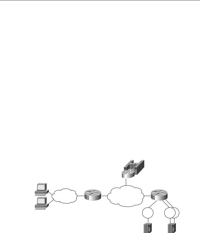
In Figure 7-3, the branch router specifies both a dlsw local-peer and a dlsw remote-peer command. The headquarters router specifies only a dlsw local-peer command, but it specifies promiscuous on the dlsw local-peer command to allow it to dynamically accept connections from branch routers.
The peer ID specified on the dlsw local-peer command is the router’s IP address. It can be a loopback address configured via interface loopback 0 or the IP address associated with a specific LAN or WAN interface. However, if you use a LAN or WAN IP address, the interface must be up for DLSw to work.
Figure 7-3 Example of dlsw local-peer and dlsw remote-peer commands.
|
|
|
|
|
|
|
|
|
|
|
|
|
|
|
|
|
Headquarters |
|||||
|
Branch router |
|
|
|
router |
|||||||||||||||||
Token |
|
|
|
|
|
|
|
|
|
|
|
|
|
|
|
|
|
|
Token |
|||
|
|
|
|
|
|
|
|
|
|
|
|
|||||||||||
Ring |
|
|
|
|
|
|
|
|
|
|
|
|
|
|
|
|
|
|
|
|
|
Ring |
|
|
|
|
|||||||||||||||||||
|
|
|
|
|
|
|
|
|
|
|
|
|
|
|
|
|
|
|
||||
|
Configuration for |
|
Configuration for |
|||||||||||||||||||
|
|
Branch router |
|
Headquarters router |
||||||||||||||||||
dlsw local-peer peer-id 10.2.24.2 |
dlsw local-peer peer-id 10.2 |
|||||||||||||||||||||
dlsw remote-peer 0 tcp 10.2.17.1 |
|
promiscuous |
||||||||||||||||||||
7-8 Cisco CCIE Fundamentals: Network Design