

Cisco. Fundamentals Network Design - Cisco Press
.pdfFrame Relay Internetwork Design
Performance concerns for specific packet-switching services include committed information rates (CIR) in Frame Relay internetworks and window size limitations in X.25 internetworks. (The CIR corresponds to the maximum average rate per connection [PVC] for a period of time.)
Frame Relay Internetwork Design
One of the chief concerns when designing a Frame Relay implementation is scalability. As your requirements for remote interconnections grow, your internetwork must be able to grow to accommodate changes. The internetwork must also provide an acceptable level of performance, while minimizing maintenance and management requirements. Meeting all these objectives simultaneously can be quite a balancing act. The discussions that follow focus on several important factors for Frame Relay internetworks:
•
•
•
•
Hierarchical design
Regional topologies
Broadcast issues
Performance issues
The guidelines and suggestions that follow are intended to provide a foundation for constructing scalable Frame Relay internetworks that balance performance, fault tolerance, and cost.
Hierarchical Design for Frame Relay Internetworks
In general, the arguments supporting hierarchical design for packet-switching networks discussed in the section “Hierarchical Design” earlier in this chapter apply to hierarchical design for Frame Relay internetworks. To review, the three factors driving the recommendation for implementing a hierarchical design are the following:
•
•
•
Scalability of hierarchical internetworks
Manageability of hierarchical internetworks
Optimization of broadcast and multicast control traffic
The method by which many Frame Relay vendors tariff services is by Data Link Connection Identifier (DLCI), which identifies a Frame Relay permanent virtual connection. A Frame Relay permanent virtual connection is equivalent to an X.25 permanent virtual circuit, which, in X.25 terminology, is identified by a logical channel number (LCN). The DLCI defines the interconnection between Frame Relay elements. For any given internetwork implementation, the number of Frame Relay permanent virtual connections is highly dependent on the protocols in use and actual traffic patterns.
How many DLCIs can be configured per serial port? It varies depending on the traffic level. You can use all of them (about 1,000), but in common use, 200–300 is a typical maximum. If you broadcast on the DLCIs, 30–50 is more realistic due to CPU overhead in generating broadcasts. Specific guidelines are difficult because overhead varies by configuration. However, on low-end boxes (4,500 and below), the architecture is bound by the available I/O memory. The specific number depends on several factors that should be considered together:
•Protocols being routed—Any broadcast-intensive protocol constrains the number of assignable DLCIs. For example, AppleTalk is a protocol that is characterized by high levels of broadcast overhead. Another example is Novell IPX, which sends both routing and service updates resulting in higher broadcast bandwidth overhead. In contrast, IGRP is less broadcast intensive
Designing Packet Service Internetworks 9-7

Frame Relay Internetwork Design
because it sends routing updates less often (by default, every 90 seconds). However, IGRP can become broadcast intensive if its IGRP timers are modified so that updates are sent more frequently.
•Broadcast traffic —Broadcasts, such as routing updates, are the single most important consideration in determining the number of DLCIs that can be defined. The amount and type of broadcast traffic will guide your ability to assign DLCIs within this general recommended range. Refer to Table 9-1 earlier in this chapter for a list of the relative level of broadcast traffic associated with common protocols.
•Speed of lines—If broadcast traffic levels are expected to be high, you should consider faster lines
and DLCIs with higher CIR and excess burst (Be) limits. You should also implement fewer DLCIs.
•Static routes—If static routing is implemented, you can use a larger number of DLCIs per line, because a larger number of DLCIs reduces the level of broadcasting.
•Size of routing protocol and SAP updates—The larger the internetwork, the larger the size of these updates. The larger the updates, the fewer the number of DLCIs that you can assign.
Two forms of hierarchical design can be implemented:
•
•
Hierarchical Meshed Frame Relay Internetworks
Hybrid Meshed Frame Relay Internetworks
Both designs have advantages and disadvantages. The brief discussions that follow contrast these two approaches.
Hierarchical Meshed Frame Relay Internetworks
The objectives of implementing a hierarchical mesh for Frame Relay environments are to avoid implementing excessively large numbers of DLCIs and to provide a manageable, segmented environment. The hierarchical meshed environment features full meshing within the core PSDN and full meshing throughout the peripheral internetworks. The hierarchy is created by strategically locating routers between internetwork elements in the hierarchy.
Figure 9-5 illustrates a simple hierarchical mesh. The internetwork illustrated in Figure 9-5 illustrates a fully meshed backbone, with meshed regional internetworks and broadcast networks at the outer periphery.
The key advantages of the hierarchical mesh are that it scales well and localizes traffic. By placing routers between fully meshed portions of the internetwork, you limit the number of DLCIs per physical interface, segment your internetwork, and make the internetwork more manageable. However, consider the following two issues when implementing a hierarchical mesh:
•Broadcast and packet replication—In an environment that has a large number of multiple DLCIs per router interface, excessive broadcast and packet replication can impair overall performance. With a high level of meshing throughout a hierarchical mesh, excessive broadcast and packet replication is a significant concern. In the backbone, where traffic throughput requirements are typically high, preventing bandwidth loss due to broadcast traffic and packet replication is particularly important.
•Increased costs associated with additional router interfaces—Compared with a fully meshed topology, additional routers are needed to separate the meshed backbone from the meshed peripheral internetworks. However, by using these routers, you can create much larger internetworks that scale almost indefinitely in comparison to a fully meshed internetwork.
9-8 Internetwork Design Guide

Hybrid Meshed Frame Relay Internetworks
Figure 9-5 Fully meshed hierarchical Frame Relay environment.
|
A1 |
|
A2 |
|
|
|
|
Router |
|
|
|
|
|
Meshed |
|
|
|
|
|
Region A |
|
|
|
|
|
Router |
|
B1 |
|
|
|
|
|
||
|
Router |
|
|
Router |
|
|
|
|
|
||
|
Meshed |
|
|
Meshed |
|
|
Frame Relay |
|
|
||
|
Router |
Router |
Region B |
||
|
backbone |
||||
|
|
|
|
||
|
Router |
|
|
Router |
|
|
|
|
|
||
|
|
|
|
B2 |
|
|
|
Router |
|
|
|
C1 |
|
Meshed |
|
C2 |
|
Router |
Region C |
Router |
|||
|
|
||||
|
|
|
Hybrid Meshed Frame Relay Internetworks
The economic and strategic importance of backbone environments often force internetwork designers to implement a hybrid meshed approach to WAN internetworks. Hybrid meshed internetworks feature redundant, meshed leased lines in the WAN backbone and partially (or fully) meshed Frame Relay PSDNs in the periphery. Routers separate the two elements. Figure 9-6 illustrates such a hybrid arrangement.
Designing Packet Service Internetworks 9-9

Frame Relay Internetwork Design
Figure 9-6 Hybrid hierarchical Frame Relay internetwork.
|
|
|
|
Access networks A1 and A2 |
|
|
|
|
|
also feature partially |
|
|
|
|
A1 |
|
meshed topology |
|
|
|
|
|
|
|
|
|
|
Router |
|
Fully meshed backbone |
Partially meshed regional |
|
|
|
|
interconnected with |
internetwork interconnected |
|
|
|
|
point-to-point leased-lines |
via Frame Relay PSDN |
|
|
|
|
Router |
|
|
|
Router |
Router |
|
|
|
|
|
|
Router |
Router |
Router |
|
|
Frame Relay |
|
|
regional network |
|||
|
Router |
Router |
|
|
|
Point-to-point |
|
A2 |
backbone |
|
|
Router |
Router |
Router |
|
Hybrid hierarchical meshes have the advantages of providing higher performance on the backbone, localizing traffic, and simplifying scaling of the internetwork. In addition, hybrid meshed internetworks for Frame Relay are attractive because they can provide better traffic control in the backbone and they allow the backbone to be made of dedicated links, resulting in greater stability.
The disadvantages of hybrid hierarchical meshes include high costs associated with the leased lines as well as broadcast and packet replication that can be significant in access internetworks.
Regional Topologies for Frame Relay Internetworks
You can adopt one of three basic design approaches for a Frame Relay-based packet service regional internetwork:
•
•
•
Star Topologies
Fully Meshed Topologies
Partially Meshed Topologies
Each of these is discussed in the following sections. In general, emphasis is placed on partially meshed topologies integrated into a hierarchical environment. Star and fully meshed topologies are discussed for structural context.
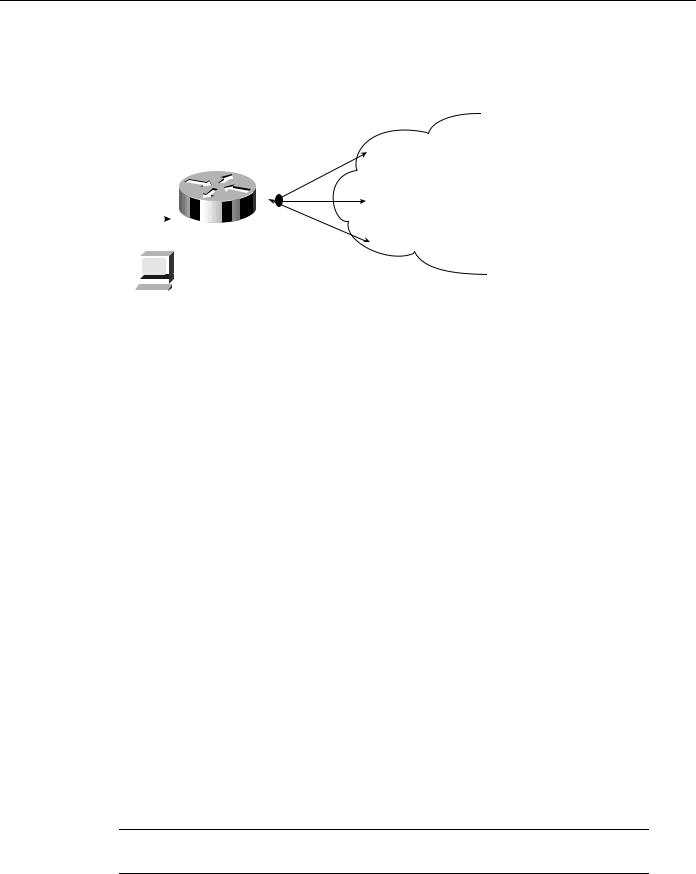
Star Topologies
The general form of the star topology is addressed in the section “Topology Design” earlier in this chapter. Stars are attractive because they minimize the number of DLCIs required and result in a low-cost solution. However, a star topology presents some inherent bandwidth limitations. Consider an environment where a backbone router is attached to a Frame Relay cloud at 256 Kbps, while the remote sites are attached at 56 Kbps. Such a topology will throttle traffic coming off the backbone intended for the remote sites.
9-10 Internetwork Design Guide

Regional Topologies for Frame Relay Internetworks
As suggested in the general discussion, a strict star topology does not offer the fault tolerance needed for many internetworking situations. If the link from the hub router to a specific leaf router is lost, all connectivity to the leaf router is lost.
Fully Meshed Topologies
A fully meshed topology mandates that every routing node connected to a Frame Relay internetwork is logically linked via an assigned DLCI to every other node on the cloud. This topology is not tenable for larger Frame Relay internetworks for several reasons:
•Large, fully meshed Frame Relay internetworks require many DLCIs. One is required for each logical link between nodes. As shown in Figure 9-7, a fully connected topology requires the assignment of [n(n-1)]/2 DLCIs, where n is the number of routers to be directly connected.
Figure 9-7 Fully meshed Frame Relay.
Router |
Router |
|
DLCIs |
Router |
Router |
•Broadcast replication will choke internetworks in large, meshed Frame Relay topologies. Routers inherently treat Frame Relay as a broadcast medium. Each time a router sends a multicast frame (such as a routing update, spanning tree update, or SAP update), the router must copy the frame to each DLCI for that Frame Relay interface.
These problems combine to make fully meshed topologies unworkable and unscalable for all but relatively small Frame Relay implementations.
Partially Meshed Topologies
Combining the concepts of the star topology and the fully meshed topology results in the partially meshed topology. Partially meshed topologies are generally recommended for Frame Relay regional environments because they offer superior fault tolerance (through redundant stars) and are less expensive than a fully meshed environment. In general, you should implement the minimum meshing to eliminate single point-of-failure risk.
Figure 9-8 illustrates a twin-star, partially meshed approach. This arrangement is supported in Frame Relay internetworks running IP, ISO CLNS, DECnet, Novell IPX, AppleTalk, and bridging.
Designing Packet Service Internetworks 9-11

Frame Relay Internetwork Design
Figure 9-8 Twin-star, partially meshed Frame Relay internetwork.
Star-1 |
Star-2 |
|
|
Router Frame Relay |
Router |
network |
|
Router |
Router |
A feature called virtual interfaces (introduced with Software Release 9.21) allows you to create internetworks using partially meshed Frame Relay designs, as shown in Figure 9-8.
To create this type of internetwork, individual physical interfaces are split into multiple virtual (logical) interfaces. The implication for Frame Relay is that DLCIs can be grouped or separated to maximize utility. For example, small fully meshed clouds of Frame Relay-connected routers can travel over a group of four DLCIs clustered on a single virtual interface, whereas a fifth DLCI on a separate virtual interface provides connectivity to a completely separate internetwork. All of this connectivity occurs over a single physical interface connected to the Frame Relay service.
Prior to Software Release 9.21, virtual interfaces were not available and partially meshed topologies posed potential problems, depending on the internetwork protocols used. Consider the topology illustrated in Figure 9-9.
Figure 9-9 Partially meshed Frame Relay internetwork.
Core A
Core Z
Frame Relay
network
Remote B
DLCIs
Remote C |
Remote D |
Given a standard router configuration and router software predating Software Release 9.21, the connectivity available in the internetwork shown in Figure 9-9 can be characterized as follows:
•
•
Core A and Core Z can reach all the remote routers.
Remote B, Remote C, and Remote D cannot reach each other.
9-12 Internetwork Design Guide

Broadcast Issues for Frame Relay Internetworks
For Frame Relay implementations running software prior to Software Release 9.21, the only way to permit connectivity among all these routers is by using a distance vector routing protocol that can disable split horizon, such as RIP or IGRP for IP. Any other internetwork protocol, such as AppleTalk or ISO CLNS, does not work. The following configuration listing illustrates an IGRP configuration to support a partially meshed arrangement.
router igrp 20 network 45.0.0.0
!
interface serial 3 encapsulation frame-relay
ip address 45.1.2.3 255.255.255.0 no ip split-horizon
This topology only works with distance vector routing protocols, assuming you want to establish connectivity from Remote B, C, or D to Core A or Core Z, but not across paths. This topology does not work with link state routing protocols because the router cannot verify complete adjacencies. Note that you will see routes and services of the leaf nodes that cannot be reached.
Broadcast Issues for Frame Relay Internetworks
Routers treat Frame Relay as a broadcast media, which means that each time the router sends a multicast frame (such as a routing update, spanning tree update, or SAP update), the router must replicate the frame to each DLCI for the Frame Relay interface. Frame replication results in substantial overhead for the router and for the physical interface.
Consider a Novell IPX environment with multiple DLCIs configured for a single physical serial interface. Every time a SAP update is detected, which occurs every 60 seconds, the router must replicate it and send it down the virtual interface associated with each DLCI. Each SAP frame contains up to seven service entries, and each update is 64 bytes. Figure 9-10 illustrates this situation.
Note One way to reduce broadcasts is to implement more efficient routing protocols, such as
Enhanced IGRP, and to adjust timers on lower speed Frame Relay services.
Figure 9-10 SAP replication in Frame Relay virtual interface environment.
|
|
DLCI 21 |
|
E0 E0 |
|
DLCI 22 |
Frame Relay network |
Router A |
S0 |
||
|
|
|
|
SAP |
|
DLCI 23 |
|
broadcast |
|
|
|
|
|
SAP broadcast is |
|
|
|
reproduced and |
|
|
|
retransmitted out |
|
Novell Server |
|
all three DLCIs |
|
|
for Interface S0 |
|
Designing Packet Service Internetworks 9-13

Frame Relay Internetwork Design
Creating a Broadcast Queue for an Interface
Very large Frame Relay networks might have performance problems when many DLCIs terminate in a single router or access server that must replicate routing updates and service advertising updates on each DLCI. The updates can consume access-link bandwidth and cause significant latency variations in user traffic; the updates can also consume interface buffers and lead to higher packet rate loss for both user data and routing updates.
To avoid such problems, you can create a special broadcast queue for an interface. The broadcast queue is managed independently of the normal interface queue, has its own buffers, and has a configurable size and service rate.
A broadcast queue is given a maximum transmission rate (throughput) limit measured in both bytes per second and packets per second. The queue is serviced to ensure that no more than this maximum is provided. The broadcast queue has priority when transmitting at a rate below the configured maximum, and hence has a guaranteed minimum bandwidth allocation. The two transmission rate limits are intended to avoid flooding the interface with broadcasts. The actual transmission rate limit in any second is the first of the two rate limits that is reached.
Performance Issues for Frame Relay Internetworks
Two important performance concerns must be addressed when you are implementing a Frame Relay internetwork:
•
•
Packet-Switched Service Provider Tariff Metrics
Multiprotocol Traffic Management Requirements
Each of these must be considered during the internetwork planning process. The following sections briefly discuss the impact that tariff metrics and multiprotocol traffic management can have on overall Frame Relay performance.
Packet-Switched Service Provider Tariff Metrics
When you contract with Frame Relay packet-switched service providers for specific capabilities, CIR, measured in bits per second, is one of the key negotiated tariff metrics. CIR is the maximum permitted traffic level that the carrier will allow on a specific DLCI into the packet-switching environment. CIR can be anything up to the capacity of the physical limitation of the connecting line.
Other key metrics are committed burst (Bc) and excess burst (Be). Bc is the number of bits that the Frame Relay internetwork is committed to accept and transmit at the CIR. Be sets the absolute limit for a DLCI in bits. This is the number of bits that the Frame Relay internetwork will attempt to transmit after Bc is accommodated. Be determines a peak or maximum Frame Relay data rate (MaxR), where MaxR = (Bc + Be)/Bc * CIR, measured in bits per second.
Consider the situation illustrated in Figure 9-11. In this environment, DLCIs 21, 22, and 23 are assigned CIRs of 56 Kbps. Assume the MaxR for each line is 112 Kbps (double the CIR). The serial line to which Router A is connected is a T1 line capable of 1.544 Mbps total throughput. Given that the type of traffic being sent into the Frame Relay internetwork consists of FTP file transfers, the potential is high that the router will attempt to transmit at a rate in excess of MaxR. If this occurs, traffic might be dropped without notification if the B e buffers (allocated at the Frame Relay switch) overflow.
9-14 Internetwork Design Guide
Performance Issues for Frame Relay Internetworks
Figure 9-11 Example of a CIR and CBR traffic limiting situation.
CIR, MaxR,and Bandwidth Specs
S0 total bandwidth = 1.544 Mbps
DLCI 21 CIR = 56 kbps
DLCI 22 CIR = 56 kbps
DLCI 23 CIR = 56 kbps
MaxR for each DLCI = 112 kbps
|
|
|
|
|
|
|
|
|
|
|
|
DLCI 21 |
|
|
|
|
|
|
E0 |
|
|
|
|
|
DLCI 22 |
|
|
|
|
|
|
|
|
|
|
|
||
|
|
|
|
|
|
|
|
|
|
|
||
|
|
|
E0 |
|
Router |
A |
|
|
S0 |
|||
|
|
|
|
|
|
|
||||||
|
|
|
|
|
|
|
|
|
|
|||
|
|
|
FTP |
DLCI 23 |
||||||||
|
|
transfers |
|
|||||||||
|
|
|
|
|
|
TCP/IP workstation |
|
|||||
|
|
|
|
|
|
|
||||||
|
|
|
|
|
|
provides FTP service |
|
|||||
|
|
|
|
|||||||||
|
|
|
|
|
|
to remote clients on |
|
|||||
|
|
|
|
|
|
|
||||||
|
|
|
|
|
|
|
||||||
|
|
TCP/IP |
Frame Relay network |
|
||||||||
workstation |
|
|||||||||||
Frame Relay network
FTP service to network clients via DLCI 21, 22, and 23
Unfortunately, there are relatively few ways to automatically prevent traffic on a line from exceeding the MaxR. Although Frame Relay itself uses the Forward Explicit Congestion Notification (FECN) and Backward Explicit Congestion Notification (BECN) protocols to control traffic in the Frame Relay internetwork, there is no formally standardized mapping between the Frame Relay (link) level and most upper-layer protocols. At this time, an FECN bit detected by a router is mapped to the congestion notification byte for DECnet Phase IV or ISO CLNS. No other protocols are supported.
The actual effect of exceeding specified CIR and derived Max R settings depends on the types of application running on the internetwork. For instance, TCP/IP’s backoff algorithm will see dropped packets as a congestion indication and sending hosts might reduce output. However, NFS has no backoff algorithm, and dropped packets will result in lost connections. When determining the CIR, Bc, and Be for Frame Relay connection, you should consider the actual line speed and applications to be supported.
Most Frame Relay carriers provide an appropriate level of buffering to handle instances when traffic exceeds the CIR for a given DLCI. These buffers allow excess packets to be spooled at the CIR and reduce packet loss, given a robust transport protocol such as TCP. Nonetheless, overflows can happen. Remember that although routers can prioritize traffic, Frame Relay switches cannot. You can specify which Frame Relay packets have low priority or low time sensitivity and will be the first to be dropped when a Frame Relay switch is congested. The mechanism that allows a Frame Relay switch to identify such packets is the discard eligibility (DE) bit.
This feature requires that the Frame Relay network be able to interpret the DE bit. Some networks take no action when the DE bit is set. Other networks use the DE bit to determine which packets to discard. The most desirable interpretation is to use the DE bit to determine which packets should be dropped first and also which packets have lower time sensitivity. You can define DE lists that identify the characteristics of packets to be eligible for discarding, and you can also specify DE groups to identify the DLCI that is affected.
You can specify DE lists based on the protocol or the interface, and on characteristics such as fragmentation of the packet, a specific TCP or User Datagram Protocol (UDP) port, an access list number, or a packet size.
Note To avoid packet loss, implement unacknowledged application protocols (such as packetized video) carefully. With these protocols, there is a greater potential for buffer overflow.
Designing Packet Service Internetworks 9-15

Frame Relay Internetwork Design
Multiprotocol Traffic Management Requirements
With multiple protocols being transmitted into a Frame Relay internetwork through a single physical interface, you might find it useful to separate traffic among different DLCIs based on protocol type. To split traffic in this way, you must assign specific protocols to specific DLCIs. This can be done by specifying static mapping on a per virtual interface basis or by defining only specific types of encapsulations for specific virtual interfaces.
Figure 9-12 illustrates the use of virtual interfaces (assigned using subinterface configuration commands) to allocate traffic to specific DLCIs. In this case, traffic of each configured protocol is sent down a specific DLCI and segregated on a per-circuit basis. In addition, each protocol can be assigned a separate CIR and a separate level of buffering by the Frame Relay service provider.
Figure 9-12 Virtual interfaces assigned specific protocols.
|
DLCI Protocol Assignments |
|
|
DLCI 21 assigned IP |
|
|
DLCI 22 assigned DECnet |
|
|
DLCI 23 assigned IPX |
|
Digital host |
|
|
Mixed protocol |
||
traffic sent to |
DLCI 21 |
|
router |
||
|
||
|
DLCI 22 |
|
E0 |
S0 |
|
|
Router C |
|
|
DLCI 23 |
|
TCP/IP |
|
|
workstation |
|
|
Frame Relay network
IP traffic sent into Frame Relay network via DLCI 21 only
DECnet traffic sent into Frame Relay network via DLCI 22 only
IPX traffic sent into Frame Relay network via DLCI 23 only
Novell Server
Figure 9-13 provides a listing of the subinterface configuration commands needed to support the configuration illustrated in Figure 9-12. The command listing in Figure 9-13 illustrates the enabling of the relevant protocols and the assignment of the protocols to the specific subinterfaces and associated Frame Relay DLCIs. Software Release 9.1 and later uses Frame Relay Inverse Address Resolution Protocol (IARP) to map protocol addresses to Frame Relay DLCIs dynamically. For that reason, Figure 9-13 does not show Frame Relay mappings.
9-16 Internetwork Design Guide