

Cisco. Fundamentals Network Design - Cisco Press
.pdfVLAN Implementation
so forth. Routing between VLANs comes automatically, without the need for an external router or card. Network address-based VLANs will mean that a single port on a switch can support more than one VLAN. This type of VLAN is also known as a virtual subnet VLAN.
•By a user-defined value —This type of VLAN is typically the most flexible, allowing VLANs to be defined based on the value of any field in a packet. For example, VLANs could be defined on
a protocol basis or could be dependent on a particular IPX or NetBIOS service. The simplest form of this type of VLAN is to group users according to their MAC addresses.
Cisco’s initial method of implementing VLANs on routers and Catalyst switches is by port. To efficiently operate and manage protocols, such as IP, IPX, and AppleTalk, all nodes in a VLAN should be in the same subnet or network.
Cisco uses three technologies to implement VLANs:
•
•
•
IEEE 802.10
Inter-Switch Link (ISL)
LAN Emulation
The three technologies are similar in that they are based on OSI Layer 2 bridge multiplexing mechanisms.
Note With respect to this chapter and the discussions in it, VLANs are differentiated by assigning each VLAN a “color” (or VLAN ID). For example, Engineering might be the “blue” VLAN, and Manufacturing might be the “green” VLAN.
IEEE 802.10
IEEE 802.10 defines a method for secure bridging of data across a shared metropolitan area network (MAN) backbone. Cisco has initially implemented the relevant portions of the standard to allow the “coloring” of bridged traffic across high-speed backbones (FDDI, Ethernet, Fast Ethernet, Token Ring, and serial links). There are two strategies using IEEE 802.10 to implement VLANs, depending on how traffic is handled through the backbone:
•
•
Switched Backbone
Routed Backbone
Switched Backbone
In the switched backbone topology shown in Figure 12-7, you want to ensure that intra-VLAN traffic goes only between Segment A and Segment D (both in VLAN 10) and Segment B and Segment C (both in VLAN 20).
Figure 12-7 IEEE 802.10 switched backbone implementation.
Segment A |
|
|
|
|
|
|
Segment B |
E0 |
|
FDDI 0 |
802.10 |
FDDI 1 |
|
E1 |
|
VLAN 10 |
|
|
|
|
VLAN 20 |
||
|
Switch |
|
|
|
Switch |
|
|
|
|
|
FDDI 2 |
|
|
|
|
|
|
E2 |
|
|
E3 |
|
|
|
Segment C |
|
|
Segment D |
|
||
|
VLAN 20 |
Switch |
VLAN 10 |
|
|||
Designing Switched LAN Internetworks 12-19
Switched LAN Network Designs
In Figure 12-7, all Ethernet ports on Switches X, Y, and Z are in a VLAN and are to be VLAN interfaces. All FDDI interfaces in Switches X, Y, and Z are called VLAN trunk interfaces. To ensure that traffic from Segment A destined for Segment D on Switch Z is forwarded onto Ethernet 3 and not onto Ethernet 2, it is colored when it leaves Switch X. Switch Z recognizes the color and knows that it must forward these frames onto Ethernet 3 and not onto Ethernet 2.
The coloring of traffic across the FDDI backbone is achieved by inserting a 16-byte header between the source MAC address and the Link Service Access Point (LSAP) of frames leaving a switch. This header contains a 4-byte VLAN ID or “color.” The receiving switch removes the header and forwards the frame to interfaces that match that VLAN color.
Routed Backbone
In the routed backbone topology shown in Figure 12–8, the goal is the same as for the switched topology—that is, to ensure that intra-VLAN traffic goes only between Segment A and Segment D (both in VLAN 10) and Segment B and Segment C (both in VLAN 20).
Figure 12-8 IEEE 802.10 routed backbone implementation.
Segment A |
|
|
|
|
|
VLAN 30 |
|
|
|
|
||||
|
VLAN 10 |
Routed |
|
|
|
|
|
|
||||||
|
|
|
||||||||||||
|
|
|
|
|
|
|
|
|
|
|
|
|
||
|
|
|
|
|
|
|
|
|
|
|
|
|
||
|
|
|
|
|
|
|
|
|
|
|
|
|
||
|
|
|
|
|
|
|
|
|
|
|
|
|
||
|
Router |
|
backbone |
|
|
Router |
|
|
|
|
|
|||
|
|
|
|
|
|
|
|
|
||||||
|
|
|
|
|
|
|
|
Router Z |
|
|
||||
|
|
Bridging path for |
|
|
|
|
|
|
|
|
|
|
Switch A1 |
|
|
|
“gluing” VLAN 10 |
|
|
|
|
|
|
|
|
|
|
||
|
|
|
|
|
|
|
|
|
|
|
|
|
||
|
|
|
|
|
|
|
|
|
|
|
|
|
|
|
|
|
|
|
Router |
|
Router Y |
|
|
|
|||||
|
|
|
|
|
|
|
|
|
VLAN 30 |
|
VLAN 30 |
|||
|
Segment C VLAN 20 |
|
|
|
|
|
|
|
||||||
|
|
|
VLAN 20 Segment B |
|
|
|||||||||
VLAN 10 Segment D
Switch X
It is important that a single VLAN use only one subnet. In Figure 12-8, VLAN 10 (subnet 10) is “split” and therefore must be “glued” together by maintaining a bridged path for it through the network. For Switch X and nodes in VLAN 20 (subnet 20), traffic is switched locally if appropriate. If traffic is destined for a node in VLAN 30 (subnet 30) from a node in VLAN 20, Router Y routes it through the backbone to Router Z. If traffic from Segment D on VLAN 10 is destined for a node in VLAN 20, Router Y routes it back out the FDDI interface.
Fast EtherChannel
Fast Ether Channel is a trunking technology based on grouping together multiple full duplex 802.3 Fast Ethernets to provide fault-tolerant high-speed links between switches, routers, and servers. Fast EtherChannels can be composed of two to four industry-standard Fast Ethernet links to provide load sharing of traffic with up to 800 Mbps of usable bandwidth. Fast EtherChannels can interconnect LAN switches, routers, servers, and clients. Since its load balancing is integrated with the Catalyst 5000 families LAN switch architectures, there is no performance degradation for adding links to a channel—high throughput and low latencies can be maintained while gaining more total available bandwidth. Fast EtherChannel provides link resiliency within a channel—if links should fail the traffic is immediately directed to the remaining links. Finally, Fast EtherChannel is not
12-20 Cisco CCIE Fundamentals: Network Design

VLAN Implementation
dependent on any type of media—it can be used with Fast Ethernet running on existing Unshielded Twisted Pair (UTP) wiring, or single mode and multimode fiber. Figure 12–9 shows a collapsed backbone topology design using the Fast EtherChannel modules to provide links of 400 Mb between switches in the wiring closets and the data center.
Figure 12-9 Collapsed backbone topology design using the Fast EtherChannel modules.
Data Center
400 Mb
400 Mb |
400 Mb |
Wiring Closets
IEEE 802.10 Design Issues
•Routers fast switch IEEE 802.10, which means that the fast-switching throughput of the platform must be considered.
•VLANs must be consistent with the routed model. (That is, subnets cannot be split.)
—If subnets must be split, they must be “glued” together by a bridged path.
—Normal routed behavior needs to be maintained for end nodes to correctly achieve routing between VLANs.
—Networks need to be designed carefully when integrating VLANs; the simplest choice is to avoid splitting VLANs across a routed backbone.
The difference between these two strategies is subtle. Table 12–3 compares the advantages and disadvantages of the two strategies.
Table 12-3 |
Advantages and Disadvantages of Switched and Routed Backbones |
|||
|
|
|
|
|
Switched Backbone |
|
Routed Backbone |
|
|
|
|
|
|
|
Advantages |
|
Disadvantages |
Advantages |
Disadvantages |
|
|
|
|
|
Propagates color |
|
Backbone is running |
No bridging in backbone. |
Color information is not |
information across entire |
bridging. |
|
propagated across backbone |
|
network. |
|
|
|
and must be configured |
|
|
|
|
manually. |
|
|
|
|
|
Allows greater scalability by |
Broadcast traffic |
Easy to integrate into |
If subnets are split, a bridged |
|
extending bridge domains. |
increases drastically on |
existing internetwork. |
path has to be set up |
|
|
|
the backbone. |
|
between switches. |
|
|
|
|
|
Can run native protocols in the backbone.
A VLAN interface can have only one VLAN ID, and VLAN trunk interfaces support multiple VLANs across them.
Designing Switched LAN Internetworks 12-21

Switched LAN Network Designs
Inter-Switch Link
ISL is a Cisco-proprietary protocol for interconnecting multiple switches and maintaining VLAN information as traffic goes between switches. This technology is similar to IEEE 802.10 in that it is a method of multiplexing bridge groups over a high-speed backbone. It is defined only on Fast Ethernet. The discussion of routing and switching in the backbone in the section “IEEE 802.10,” earlier in this chapter, also applies to ISL.
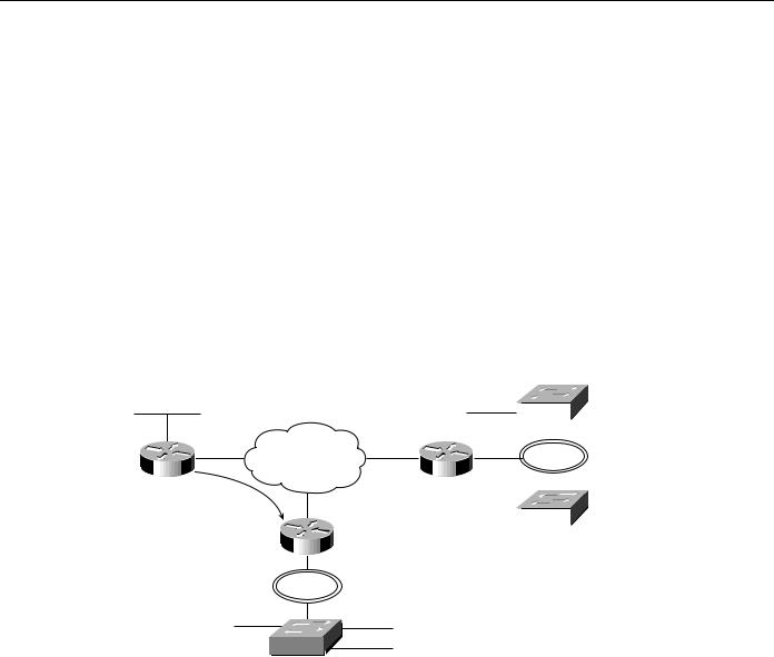
With ISL, an Ethernet frame is encapsulated with a header that maintains VLAN IDs between switches. A 30-byte header is prepended to the Ethernet frame, and it contains a two-byte VLAN ID. In Figure 12–10, Switch Y switches VLAN 20 traffic between segments A and B if appropriate. Otherwise, it encapsulates traffic with an ISL header that identifies it as traffic for VLAN 20 and sends it through the interim switch to Router X.
Figure 12-10 Inter-switch link design.
|
|
|
|
|
|
|
Router X |
|
|
|
|
|||
|
|
|
|
100 Mbps |
|
Router |
|
|
100 Mbps |
|
|
|||
|
|
|
|
|
|
|
|
|
||||||
|
|
|
|
|
|
|
|
|
|
|||||
|
|
|
|
|
ISL |
|
|
|
|
ISL |
|
|
||
VLAN 10 |
|
|
|
|
|
|
|
|
|
|
|
|
|
|
|
|
|
|
|
|
|
|
|
|
|
|
|
|
|
|
|
|
|
|
|
|
|
|
|
|
|
|
|
|
|
Switch X |
|
|
|
|
|
|
|
Switch Z |
VLAN 20 |
||||
|
|
|
|
|
|
|
|
|
|
|||||
|
|
|
100 Mbps ISL |
|
|
|
|
|
|
|
|
|||
Segment A VLAN 20 |
|
|
|
VLAN 20 |
Segment B |
|
|
|
|
|||||
|
|
|
|
|
|
|
|
|
|
|
|
|
|
|
|
|
|
|
|
|
|
|
|
|
|
|
|
|
|
10 Mbps Ethernet |
Switch Y |
|
VLAN 10 |
|
|
|
|
|
|
|
|
|||
|
|
|
|
|
|
|
|
|
|
|
||||
Router X routes the packet to the appropriate interface, which could be through a routed network beyond Router X (as in this case) out the Fast Ethernet interface to Switch Z. Switch Z receives the packet, examines the ISL header noting that this packet is destined for VLAN 20, and switches it to all ports in VLAN 20 (if the packet is a broadcast or multicast) or the appropriate port (if the packet is a unicast).
Note Routers fast switch ISL, which means that the fast-switching throughput of the platform must be considered.
LAN Emulation
LAN Emulation (LANE) is a service that provides interoperability between ATM-based workstations and devices connected to existing legacy LAN technology. The ATM Forum has defined a standard for LANE that provides to workstations attached via ATM the same capabilities that they are used to obtaining from legacy LANs.
LANE uses MAC encapsulation (OSI Layer 2) because this approach supports the largest number of existing OSI Layer 3 protocols. The end result is that all devices attached to an emulated LAN appear to be on one bridged segment. In this way, AppleTalk, IPX, and other protocols should have similar performance characteristics as in a traditional bridged environment. In ATM LANE environments, the ATM switch handles traffic that belongs to the same emulated LAN (ELAN), and routers handle inter-ELAN traffic. For more information about LANE, see Chapter 8, “Designing ATM Internetworks.”
12-22 Cisco CCIE Fundamentals: Network Design

VLAN Implementation
Virtual Multihomed Servers
In traditional networks, there are usually several well-known servers, such as e-mail and corporate servers, that almost everyone in an enterprise needs to access. If these servers are located in only one VLAN, the benefits of VLANs will be lost because all of the different workgroups will be forced to route to access this common information source.
This problem can be solved with LANE and virtual multihomed servers, as shown in Figure 12–11. Network interface cards (NICs) allow workstations and servers to join up to eight different VLANs. This means that the server will appear in eight different ELANs and that to other members of each ELAN, the server appears to be like any other member. This capability greatly increases the performance of the network as a whole because common information is available directly through the optimal Data Direct VCC and does not need to be routed. This also means that the server must process all broadcast traffic in each VLAN that it belongs to, which can decrease performance.
Figure 12-11 Multihomed servers in an ATM network.
This server appears to be a member of each ELAN by running a LEC  for each ELAN.
Router |
ELAN 1 |
Router |
ATM switch
ELAN 3
ELAN 2
ATM LAN/workgroup switches
To multihome servers in non-ATM environments, there are two possible choices:
•Use servers with multiple NICs (different connections into each VLAN).
•Use servers with NICs that support the VLAN trunking technology (IEEE 802.10 or ISL) used in the backbone.
Virtual Trunk Protocol
The Catalyst 5000 switch implements Cisco’s Virtual Trunk Protocol (VTP). VTP is the industry’s first protocol implementation specifically designed for large VLAN deployments. VTP enhances VLAN deployment by providing the following:
•
•
•
•
Integration of ISL, 802.10, and ATM LAN-based VLANs
Auto-intelligence within the switches for configuring VLANs
Configuration consistency across the network
An automapping scheme for going across mixed-media backbones
Designing Switched LAN Internetworks 12-23

Switched LAN Network Designs
•Accurate tracking and monitoring of VLANs
•Dynamic reporting of added VLANs across the network
•Plug-and-play setup and configuration when adding new VLANs
General Network Design Principles
Good network design is based on many concepts that are summarized by the following key principles:
•Examine single points of failure carefully—There should be redundancy in the network so that a single failure does not isolate any portion of the network. There are two aspects of redundancy that need to be considered: backup and load balancing. In the event of a failure in the network, there should be an alternative or backup path. Load balancing occurs when two or more paths to a destination exist and can be utilized depending on the network load. The level of redundancy required in a particular network varies from network to network.
•Characterize application and protocol traffic —For example, the flow of application data will profile client-server interaction and is crucial for efficient resource allocation, such as the number of clients using a particular server or the number of client workstations on a segment.
•Analyze bandwidth availability—For example, there should not be an order of magnitude difference between the different layers of the hierarchical model. It is important to remember that the hierarchical model refers to conceptual layers that provide functionality. The actual demarcation between layers does not have to be a physical link—it can be the backplane of a particular device.
•Build networks using a hierarchical or modular model—The hierarchy allows autonomous segments to be internetworked together.
Figure 12–12 shows a high-level view of the various aspects of a hierarchical network design. A hierarchical network design presents three layers—core, distribution, and access—with each layer providing different functionality.
The core layer is a high-speed switching backbone and should be designed to switch packets as fast as possible. This layer of the network should not perform any packet manipulation access lists and filtering that would slow down the switching of packets.
The distribution layer of the network is the demarcation point between the access and core layers and helps to define and differentiate the core. The purpose of this layer is to provide boundary definition and is the place at which packet manipulation can take place. In the campus environment, the distribution layer can include several functions, such as the following:
•
•
•
•
•
•
Address or area aggregation
Departmental or workgroup access
Broadcast/multicast domain definition
VLAN routing
Any media transitions that need to occur
Security
12-24 Cisco CCIE Fundamentals: Network Design

General Network Design Principles
Figure 12-12 Hierarchical network design model.
Core
Distribution
High-speed switching
Access
Policy-based connectivity
Local and remote workgroup access
In the non-campus environment, the distribution layer can be a redistribution point between routing domains or the demarcation between static and dynamic routing protocols. It can also be the point at which remote sites access the corporate network. The distribution layer can be summarized as the layer that provides policy-based connectivity.
The access layer is the point at which local end users are allowed into the network. This layer may also use access lists or filters to further optimize the needs of a particular set of users. In the campus environment, access-layer functions can include the following:
•
•
•
•
Shared bandwidth
Switched bandwidth
MAC layer filtering
Microsegmentation
In the non-campus environment, the access layer can give remote sites access to the corporate network via some wide-area technology, such as Frame Relay, ISDN, or leased lines.
It is sometimes mistakenly thought that the three layers (core, distribution, and access) must exist in clear and distinct physical entities, but this does not have to be the case. The layers are defined to aid successful network design and to represent functionality that must exist in a network. The instantiation of each layer can be in distinct routers or switches, can be represented by a physical media, can be combined in a single device, or can be omitted altogether. The way the layers are implemented depends on the needs of the network being designed. Note, however, that for a network to function optimally, hierarchy must be maintained.
With respect to the hierarchical model, traditional campus LANs have followed one of two designs—single router and distributed backbone—as shown in Figure 12–13.
Designing Switched LAN Internetworks 12-25

Switched LAN Network Designs
Figure 12-13 Traditional campus design.
Core
FDDI dual ring
Distribution |
Router |
Router |
Router |
Access
|
|
|
|
|
|
|
|
|
|
|
|
|
|
|
|
|
|
|
|
|
|
|
|
|
|
|
|
|
|
|
|
|
|
|
|
|
|
|
|
|
|
|
|
|
|
|
|
Single-router design |
|
|
|
|
|
Distributed backbone design |
In the single-router design, the core and distribution layers are present in a single entity—the router. Core functionality is represented by the backplane of the router and distribution is represented by the router. Access for end users is through individualor chassis-based hubs. This design suffers from scalability constraints because the router can be only be in one physical location, so all segments end at the same location—the router. The single router is responsible for all distribution functionality, which can cause CPU overload.
The distributed backbone design uses a high-speed backbone media, typically FDDI, to spread routing functionality among several routers. This also allows the backbone to traverse floors, a building, or a campus.
Switched LAN Network Design Principles
When designing switched LAN campus networks, the following factors must be considered:
•Broadcast radiation—Broadcast radiation can become fatal—that is, 100 percent of host CPU cycles can be consumed by processing broadcast and multicast packets. Because of delays inherent in carrier sense multiple access collision detect (CMSA/CD) technologies, such as Ethernet, any more than a small amount of broadcast traffic will adversely affect the operation of devices attached to a switch. Although VLANs reduce the effect of broadcast radiation on all LANs, there is still a scaling issue as to how many hosts should reside on a given VLAN. A router allows for larger network designs because a VLAN can be subsegmented depending on traffic patterns. However, in a nonoptimal network design, a single router can be burdened with large amounts of traffic.
•Well-behaved VLANs—A well-behaved VLAN is a VLAN in which 80 percent or more of the traffic is local to that VLAN. In an example in which the Marketing, MIS, and Engineering departments each have an individual VLAN segment, the 80 percent rule is violated when a user in the Marketing VLAN reads mail from the MIS VLAN, mounts servers from the Engineering VLAN, and sends e-mail to members of the Engineering VLAN.
•Available bandwidth to access routing functionality—Inter-VLAN traffic must be routed, so the network design must allocate enough bandwidth to move inter-VLAN traffic from the source, through the device that provides routing functionality, and to the destination.
•Appropriate placement of administrative boundaries—Switching has the effect of flattening networks, and the deployment of switching outside of your administrative boundary can adversely affect the network within your administrative boundary.
12-26 Cisco CCIE Fundamentals: Network Design

Switched LAN Network Design Principles
Campus network designs are evolving rapidly with the deployment of switching at all levels of the network—from the desktop to the backbone. Three topologies have emerged as generic network designs:
•
•
•
Scaled Switching
Large Switching/Minimal Routing
Distributed Routing/Switching
Scaled Switching
The scaled switching design shown in Figure 12–14 deploys switching at all levels of the network without the use of routers. In this design, each layer consists of switches, with switches in the access layer providing 10-Mbps Ethernet or 16-Mbps Token Ring to end users.
Figure 12-14 |
Scaled switching design. |
|||||||||||
Core |
|
|
|
|
|
|
|
|
|
|
Switches |
|
|
|
|
|
|
|
|
|
|
|
|
|
|
|
|
100 Mbps |
||||||||||
Distribution |
|
|
|
|
|
|
|
|
|
|
Switches |
|
|
|
|
|
|
|
|
|
|
||||
|
|
|
|
|
|
|
|
|
|
|
||
100 Mbps |
||||||||||||
Access |
|
|
|
|
|
|
|
|
|
|
Switches |
|
|
|
|
|
|
|
|
|
|
|
|
|
|
10-Mbps Ethernet or 16-Mbps Token Ring
Scaled switching is a low-cost and easy-to-install solution for a small campus network. It does not require knowledge of address structure, is easy to manage, and allows all users to communicate with one another. However, this network comprises a single broadcast domain. If a scaled switched network needs to grow beyond the broadcast domain, it can use VLANs to create multiple broadcast domains. Note that when VLANs are used, end users in one VLAN cannot communicate with end users in another VLAN unless routers are deployed.
Large Switched/Minimal Routing
The large switched/minimal routing design deploys switching at the access layer of the network, either ATM switching or LAN switching at the distribution layer of the network, and ATM/LAN switching at the core. Figure 12–15 shows an example of this network design.
Designing Switched LAN Internetworks 12-27

Switched LAN Network Designs
Figure 12-15 |
Large switched/minimal routing design. |
|
Core |
Switches |
Switches |
|
155 Mbps |
100 Mbps |
Distribution |
|
|
|
Router |
|
|
|
Router |
|
Router |
|
|
155 Mbps |
100 Mbps |
Switches |
Switches |
|
155 Mbps |
100 Mbps |
|
Access |
|
|
10-Mbps Ethernet |
Switches |
|
|
or 16-Mbps Token Ring |
|
In the case of ATM in the distribution layer, the following key issues are relevant:
•LANE support on routers and switches.
•Support for UNI 3.X signaling (including point-to-multipoint).
•If redundancy is provided by a virtual PVC or SVC mesh, the mesh is a single point of failure. In the case of LAN switching in the distribution layer, the following key issues are relevant:
•Support for VLAN trunking technology in each device.
•The switches in the distribution layer must run the Spanning-Tree Protocol to prevent loops, which means that some connections will be blocked and load balancing cannot occur.
To scale the large switched/minimal routing design, a logical hierarchy must be imposed. The logical hierarchy consists of VLANs and routers that enable inter-VLAN communication. In this topology, routing is used only in the distribution layer, and the access layer depends on bandwidth through the distribution layer to gain access to high-speed switching functionality in the core layer.
The large switched/minimal routing design scales well when VLANs are designed so that the majority of resources are available in the VLAN. Therefore, if this topology can be designed so that 80 percent of traffic is intra-VLAN and only 20 percent of traffic is inter-VLAN, the bandwidth needed for inter-VLAN routing is not a concern. However, if inter-VLAN traffic is greater than
20 percent, access to routing in the core becomes a scalability issue. For optimal network operation, scalable routing content is needed at the distribution layer of the network.
Distributed Routing/Switching
The distributed routing/switching design deploys switching in the access layer, routing in the distribution layer, and some form of high-speed switching in the core layer, as shown in Figure 12–16.
12-28 Cisco CCIE Fundamentals: Network Design