

Cisco. Fundamentals Network Design - Cisco Press
.pdfC H A P T E R 8
Designing ATM Internetworks
This chapter describes current Asynchronous Transfer Mode (ATM) technologies that network designers can use in their networks today. It also makes recommendations for designing non-ATM networks so that those networks can take advantage of ATM in the future without sacrificing current investments in cable.
This chapter focuses on the following topics:
•
•
ATM overview
Cisco’s ATM WAN solutions
ATM Defined
ATM is an evolving technology designed for the high-speed transfer of voice, video, and data through public and private networks in a cost-effective manner. ATM is based on the efforts of Study Group XVIII of the International Telecommunication Union Telecommunication Standardization Sector (ITU-T, formerly the Consultative Committee for International Telegraph and Telephone [CCITT]) and the American National Standards Institute (ANSI) to apply very large-scale integration (VLSI) technology to the transfer of data within public networks. Officially, the ATM layer of the Broadband Integrated Services Digital Network (BISDN) model is defined by
CCITT I.361.
Current efforts to bring ATM technology to private networks and to guarantee interoperability between private and public networks is being done by the ATM Forum, which was jointly founded by Cisco Systems, NET/ADAPTIVE, Northern Telecom, and Sprint in 1991.
Role of ATM in Internetworks
Today, 90 percent of computing power resides on desktops, and that power is growing exponentially. Distributed applications are increasingly bandwidth-hungry, and the emergence of the Internet is driving most LAN architectures to the limit. Voice communications have increased significantly with increasing reliance on centralized voice mail systems for verbal communications. The internetwork is the critical tool for information flow. Internetworks are being pressured to cost less yet support the emerging applications and higher number of users with increased performance.
To date, local and wide-area communications have remained logically separate. In the LAN, bandwidth is free and connectivity is limited only by hardware and implementation cost. The LAN has carried data only. In the WAN, bandwidth has been the overriding cost, and such delay-sensitive traffic as voice has remained separate from data. New applications and the economics of supporting them, however, are forcing these conventions to change.
Designing ATM Internetworks 8-1
Role of ATM in Internetworks
The Internet is the first source of multimedia to the desktop and immediately breaks the rules. Such Internet applications as voice and real-time video require better, more predictable LAN and WAN performance. In addition, the Internet also necessitates that the WAN recognize the traffic in the LAN stream, thereby driving LAN/WAN integration.
Multiservice Networks
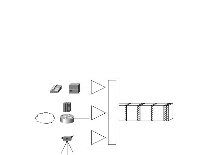
ATM has emerged as one of the technologies for integrating LANs and WANs. ATM can support any traffic type in separate or mixed streams, delay-sensitive traffic, and nondelay-sensitive traffic, as shown in Figure 8-1.
Figure 8-1 ATM support of various traffic types.
PBX |
|
|
|
Circuit |
|
Streams |
|
|
FEP |
|
Cell switching |
SNA |
|
|
Frames |
Packet |
Q |
LAN |
|
|
|
|
Cells |
Cells |
ATM |
|
|
|
ATM can also scale from low to high speeds. It has been adopted by all the industry’s equipment vendors, from LAN to private branch exchange (PBX). With ATM, network designers can integrate LANs and WANs, support emerging applications with economy in the enterprise, and support legacy protocols with added efficiency.
TDM Network Migration
In addition to using ATM to combine multiple networks into one multiservice network, network designers are deploying ATM technology to migrate from TDM networks for the following reasons:
•
•
•
To reduce WAN bandwidth cost
To improve performance
To reduce downtime
Reduced WAN Bandwidth Cost
The Cisco line of ATM switches provide additional bandwidth through the use of voice compression, silence compression, repetitive pattern suppression, and dynamic bandwidth allocation. The Cisco implementation of ATM combines the strengths of TDM—whose fixed time slots are used by
8-2 Cisco CCIE Fundamentals: Network Design

Integrated Solutions
telephone companies to deliver voice without distortion—with the strengths of packet-switching data networks—whose variable size data units are used by computer networks, such as the Internet, to deliver data efficiently.
While building on the strengths of TDM, ATM avoids the weaknesses of TDM (which wastes bandwidth by transmitting the fixed time slots even when no one is speaking) and PSDNs (which cannot accommodate time-sensitive traffic, such as voice and video, because PSDNs are designed for transmitting bursty data). By using fixed-size cells, ATM combines the isochronicity of TDM with the efficiency of PSDN.
Improved Performance
ATM offers improved performance through performance guarantees and robust WAN traffic management that support the following capabilities:
•Large buffers that guarantee Quality of Service (QoS) for bursty data traffic and demanding multimedia applications
•
•
Per-virtual circuit (VC) queuing and rate scheduling
Feedback—congestion notification
Reduced Downtime
ATM offers high reliability, thereby reducing downtime. This high reliability is available because of the following ATM capabilities:
•
•
The capability to support redundant processors, port and trunk interfaces, and power supplies
The capability to rapidly reroute around failed trunks
Integrated Solutions
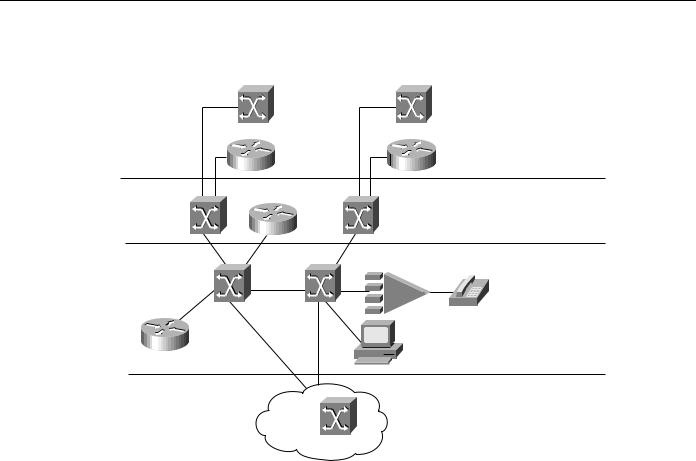
The trend in internetworking is to provide network designers greater flexibility in solving multiple internetworking problems without creating multiple networks or writing off existing data communications investments. Routers can provide a reliable, secure network and act as a barrier against inadvertent broadcast storms in the local networks. Switches, which can be divided into two main categories—LAN switches and WAN switches—can be deployed at the workgroup, campus backbone, or WAN level, as shown in Figure 8-2.
Designing ATM Internetworks 8-3
Different Types of ATM Switches
Figure 8-2 The role of ATM switches in an internetwork.
LightStream 1010 |
LightStream 1010 |
|
|
Catalyst |
|
Workgroup ATM |
|
LAN |
|
||
|
|
||
switches |
|
|
|
LightStream |
LightStream |
Campus ATM |
|
1010 |
1010 |
||
|
|||
StrataCom |
Service multiplexer |
|
|
LightStream |
|
|
|
1010 |
|
|
Enterprise ATM
Cisco routers
Multiservice Access ATM
WAN
StrataCom
Underlying and integrating all Cisco products is the Cisco IOS software.The Cisco IOS software enables disparate groups, diverse devices, and multiple protocols all to be integrated into a highly reliable and scalable network.
Different Types of ATM Switches
Even though all ATM switches perform cell relay, ATM switches differ markedly in the following ways:
•
•
•
•
Variety of interfaces and services that are supported
Redundancy
Depth of ATM internetworking software
Sophistication of traffic management mechanism
Just as there are routers and LAN switches available at various price/performance points with different levels of functionality, ATM switches can be segmented into the following four distinct types that reflect the needs of particular applications and markets:
•
•
•
•
Workgroup ATM switches
Campus ATM switches
Enterprise ATM switches
Multiservice access switches
As Figure 8-2 shows, Cisco offers a complete range of ATM switches.
8-4 Cisco CCIE Fundamentals: Network Design

Workgroup and Campus ATM Switches
Workgroup and Campus ATM Switches
Workgroup ATM switches are characterized by having Ethernet switch ports and an ATM uplink to connect to a campus ATM switch. An example of a workgroup ATM switch is the Cisco
Catalyst 5000.
The Catalyst 5500 switch provides high-performance switching between workstations, servers, switches, and routers in wiring closet, workgroup, and campus backbone environments.
The Catalyst 5500 LAN is a 13-slot switch. Slot 1 is reserved for the supervisor engine module, which provides switching, local and remote management, and dual Fast Ethernet uplinks. Slot 2 is available for a second, redundant supervisor engine, or any of the other supported modules. Slots 3–12 support any of the supported modules.
Slot 13 can be populated only with a LightStream 1010 ATM Switch Processor (ASP). If an ASP is present in slot 13, slots 9–12 support any of the standard LightStream 1010 ATM switch port adapter modules (PAMs).
The Catalyst 5500 has a 3.6-Gbps media-independent switch fabric and a 5-Gbps cell-switch fabric. The backplane provides the connection between power supplies, supervisor engine, interface modules, and backbone module. The 3.6-Gbps media-independent fabric supports Ethernet, Fast Ethernet, FDDI/CDDI, ATM LAN Emulation, and RSM modules. The 5-Gbps cell-based fabric supports a LightStream 1010 ASP module and ATM PAMs.
Campus ATM switches are generally used for small-scale ATM backbones (for instance, to link ATM routers or LAN switches). This use of ATM switches can alleviate current backbone congestion while enabling the deployment of such new services as virtual LANs (VLANs). Campus switches need to support a wide variety of both local backbone and WAN types but be price/performance optimized for the local backbone function. In this class of switches, ATM routing capabilities that allow multiple switches to be tied together is very important. Congestion control mechanisms for optimizing backbone performance is also important. The LightStream 1010 family of ATM switches is an example of a campus ATM switch. For more information on deploying workgroup and campus ATM switches in your internetwork, see Chapter 12, “Designing Switched LAN Internetworks.”
Enterprise ATM Switches
Enterprise ATM switches are sophisticated multiservice devices that are designed to form the core backbones of large, enterprise networks. They are intended to complement the role played by today’s high-end multiprotocol routers. Enterprise ATM switches are used to interconnect campus ATM switches. Enterprise-class switches, however, can act not only as ATM backbones but can serve as the single point of integration for all of the disparate services and technology found in enterprise backbones today. By integrating all of these services onto a common platform and a common ATM transport infrastructure, network designers can gain greater manageability and eliminate the need for multiple overlay networks.
Cisco’s BPX/AXIS is a powerful broadband ATM switch designed to meet the demanding, high-traffic needs of a large private enterprise or public service provider. This chapter focuses on this category of ATM switches.
Multiservice Access Switches
Beyond private networks, ATM platforms will also be widely deployed by service providers both as customer premises equipment (CPE) and within public networks. Such equipment will be used to support multiple MAN and WAN services—for instance, Frame Relay switching, LAN
Designing ATM Internetworks 8-5
ATM Overview
interconnect, or public ATM services—on a common ATM infrastructure. Enterprise ATM switches will often be used in these public network applications because of their emphasis on high availability and redundancy, their support of multiple interfaces, and capability to integrate voice and data.
ATM Overview
This section discusses the following ATM concepts:
•
•
•
•
•
Structure of an ATM Network
ATM Functional Layers
ATM Addressing
ATM Media
ATM Data Exchange Interface
Structure of an ATM Network
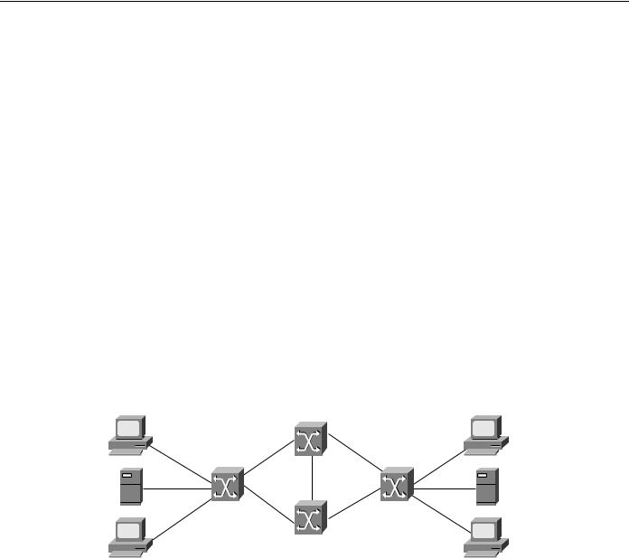
ATM is based on the concept of two end-point devices communicating by means of intermediate switches. As Figure 8-3 shows, an ATM network is made up of a series of switches and end-point devices. The end-point devices can be ATM-attached end stations, ATM-attached servers, or ATM-attached routers.
Figure 8-3 Components of an ATM network.
UNI |
NNI |
UNI = User-to-Network Interface
NNI = Network-to-Network Interface
As Figure 8-3 shows, there are two types of interfaces in an ATM network:
•
•
User-to-Network Interface (UNI)
Network-to-Network Interface (NNI)
The UNI connection is made up of an end-point device and a private or public ATM switch. The NNI is the connection between two ATM switches. The UNI and NNI connections can be carried by different physical connections.
In addition to the UNI and NNI protocols, the ATM Forum has defined a set of LAN Emulation (LANE) standards and a Private Network to Network Interface (PNNI) Phase 0 protocol. LANE is a technology network designers can use to internetwork legacy LANs such as Ethernet and Token Ring with ATM-attached devices. Most LANE networks consist of multiple ATM switches and typically employ the PNNI protocol.
8-6 Cisco CCIE Fundamentals: Network Design
Structure of an ATM Network
The full PNNI 1.0 specification was released by the ATM Forum in May 1996. It enables extremely scalable, full function, dynamic multi-vendor ATM networks by providing both PNNI routing and PNNI signaling. PNNI is based on UNI 3.0 signaling and static routes. The section "Role of LANE" later in this chapter discusses ATM LANE networks in detail.
General Operation on an ATM Network
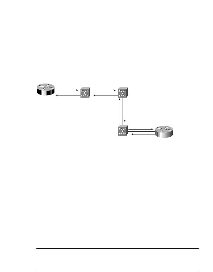
Because ATM is connection-oriented, a connection must be established between two end points before any data transfer can occur. This connection is accomplished through a signaling protocol as shown in Figure 8-4.
Figure 8-4 Establishing a connection in an ATM network.
|
|
|
|
|
|
ATM switch 1 |
ATM switch 2 |
|||||||
|
Router |
|
A |
|
|
Connect to B? |
Connect to B? |
|
|
|||||
|
|
|
|
|
|
|||||||||
|
|
|
|
|
|
|
|
|
|
|
|
|
||
|
|
|
|
|
|
|
|
|
|
|
|
|
||
Yes |
|
Yes |
|
Connect to B? |
||||||||||
|
|
|
|
|
|
|
|
|||||||
|
|
|
|
|
|
|
|
|||||||
|
|
|
|
|
|
|
|
|||||||
|
|
|
|
|
|
|
|
|
|
Yes |
|
|||
|
|
|
|
|
|
|
|
|
|
|
|
|
|
|
Connect to B? |
|
Yes |
Router B |
|
ATM switch 3
As Figure 8-4 shows, for Router A to connect to Router B the following must occur:
1 Router A sends a signaling request packet to its directly connected ATM switch (ATM Switch 1).
This request contains the ATM address of the Router B as well as any QoS parameters required for the connection.
2ATM Switch 1 reassembles the signaling packet from Router A, and then examines it.
3If ATM Switch 1 has an entry for Router B’s ATM address in its switch table and it can accommodate the QoS requested for the connection, it sets up the virtual connection and forwards the request to the next switch (ATM Switch 2) along the path.
4Every switch along the path to Router B reassembles and examines the signaling packet, and then forwards it to the next switch if the QoS parameters can be supported. Each switch also sets up the virtual connection as the signaling packet is forwarded.
If any switch along the path cannot accommodate the requested QoS parameters, the request is rejected and a rejection message is sent back to Router A.
5When the signaling packet arrives at Router B, Router B reassembles it and evaluates the packet. If Router B can support the requested QoS, it responds with an accept message. As the accept message is propagated back to Router A, the switches set up a virtual circuit.
Note A virtual channel is equivalent to a virtual circuit—that is, both terms describe a logical connection between the two ends of a communications connection. A virtual path is a logical grouping of virtual circuits that allows an ATM switch to perform operations on groups of virtual circuits.
Designing ATM Internetworks 8-7

ATM Overview
6Router A receives the accept message from its directly connected ATM switch (ATM Switch 1), as well as the Virtual path identifier (VPI) and Virtual channel identifier (VCI) values that it should use for cells sent to Router B.
Note ATM cells consist of five bytes of header information and 48 bytes of payload data. The VPI and VCI fields in the ATM header are used to route cells through ATM networks. The VPI and VCI fields of the cell header identify the next network segment that a cell needs to transmit on its way to its final destination.
ATM Functional Layers
Just as the Open System Interconnection (OSI) reference model describes how two computers communicate over a network, the ATM protocol model describes how two end systems communicate through ATM switches. The ATM protocol model consists of the following three functional layers:
•
•
•
ATM physical layer
ATM layer
ATM adaptation layer
As Figure 8-5 shows, these three layers correspond roughly to Layer 1 and parts of Layer 2 (such as error control and data framing) of the OSI reference model.
Figure 8-5 Relationship of ATM functional layers to the OSI reference model.
Application
Network
ATM adapation |
|
Data Link |
layers |
|
|
|
|
|
ATM layer |
|
|
|
|
|
ATM physical layer |
|
Physical |
|
|
|
ATM layers |
|
OSI layers |
Physical Layer
The ATM physical layer controls transmission and receipt of bits on the physical medium. It also keeps track of ATM cell boundaries and packages cells into the appropriate type of frame for the physical medium being used. The ATM physical layer is divided into two parts:
•
•
Physical medium sublayer
Transmission convergence sublayer
8-8 Cisco CCIE Fundamentals: Network Design

ATM Functional Layers
Physical Medium Sublayer
The physical medium sublayer is responsible for sending and receiving a continuous flow of bits with associated timing information to synchronize transmission and reception. Because it includes only physical-medium-dependent functions, its specification depends on the physical medium used. ATM can use any physical medium capable of carrying ATM cells. Some existing standards that can carry ATM cells are SONET (Synchronous Optical Network)/SDH, DS-3/E3, 100-Mbps local fiber (Fiber Distributed Data Interface [FDDI] physical layer), and 155-Mbps local fiber (Fiber Channel physical layer). Various proposals for use over twisted-pair wire are also under consideration.
Transmission Convergence Sublayer
The transmission convergence sublayer is responsible for the following:
•
•
Cell delineation—Maintains ATM cell boundaries.
Header error control sequence generation and verification —Generates and checks the header error control code to ensure valid data.
•Cell rate decoupling—Inserts or suppresses idle (unassigned) ATM cells to adapt the rate of valid ATM cells to the payload capacity of the transmission system.
•Transmission frame adaptation—Packages ATM cells into frames acceptable to the particular physical-layer implementation.
•Transmission frame generation and recovery—Generates and maintains the appropriate physical-layer frame structure.
ATM Layer
The ATM layer establishes virtual connections and passes ATM cells through the ATM network. To do this, it uses the information contained in the header of each ATM cell. The ATM layer is responsible for performing the following four basic functions:
•Multiplexing and demultiplexing the cells of different virtual connections. These connections are identified by their VCI and VPI values.
•Translating the values of the VCI and VPI at the ATM switches or cross connects.
•Extracting and inserting the header before or after the cell is delivered to or from the higher ATM adaptation layer.
•Handling the implementation of a flow control mechanism at the UNI.
ATM Adaptation Layer (AAL)
The AAL translates between the larger service data units (SDUs) (for example, video streams and data packets) of upper-layer processes and ATM cells. Specifically, the AAL receives packets from upper-level protocols (such as AppleTalk, Internet Protocols [IP], and NetWare) and breaks them into the 48-byte segments that form the payload field of an ATM cell. Several ATM adaptation layers are currently specified. Table 8-1 summarizes the characteristics of each AAL.
Table 8-1 |
ATM Adapter Layers |
|
|
|
|
|
|
|
|
|
|
Characteristics |
|
AAL1 |
AAL3/4 |
AAL4 |
AAL5 |
|
|
|
|
|
|
Requires timing between |
Yes |
No |
No |
No |
|
source and destination |
|
|
|
|
|
|
|
|
|
|
|
Designing ATM Internetworks 8-9

ATM Overview
Characteristics |
AAL1 |
AAL3/4 |
AAL4 |
AAL5 |
Data rate |
Constant |
Variable |
Variable |
Variable |
|
|
|
|
|
Connection mode |
Connection- |
Connection- |
Connectionless |
Connection- |
|
oriented |
oriented |
|
oriented |
|
|
|
|
|
Traffic types |
Voice and circuit emulation |
Data |
Data |
Data |
|
|
|
|
|
AAL1
AAL1 prepares a cell for transmission. The payload data consists of a synchronous sample (for example, one byte of data generated at a sampling rate of 125 microseconds). The sequence number field (SN) and sequence number protection (SNP) fields provide the information that the receiving AAL1 needs to verify that it has received the cells in the correct order. The rest of the payload field is filled with enough single bytes to equal 48 bytes.
AAL1 is appropriate for transporting telephone traffic and uncompressed video traffic. It requires timing synchronization between the source and destination and, for that reason, depends on a media that supports clocking, such as SONET. The standards for supporting clock recovery are currently being defined.
AAL3/4
AAL3/4 was designed for network service providers and is closely aligned with Switched Multimegabit Data Service (SMDS). AAL3/4 is used to transmit SMDS packets over an ATM network. The convergence sublayer (CS) creates a protocol data unit (PDU) by prepending a Beginning/End Tag header to the frame and appending a length field as a trailer as shown in Figure 8-6.
Figure 8-6 AAL3/4 cell preparation.
Frame |
|
CS PDU |
Convergence |
|
sublayer |
 SAR PDU
 SAR PDU
SAR PDU |
SAR sublayer |
|
|
|
SAR PDU |
ATM cell Hdr  Payload
ATM cell Hdr  Payload
ATM cell Hdr  Payload
ATM cell Hdr  Payload
The segmentation and reassembly (SAR) sublayer fragments the PDU and prepends to each PDU fragment a header consisting of the following fields:
•Type—Identifies whether the cell is the beginning of a message, continuation of a message, or end of a message.
•Sequence number—Identifies the order in which cells should be reassembled.
8-10 Cisco CCIE Fundamentals: Network Design