

Cisco. Fundamentals Network Design - Cisco Press
.pdfSDLLC Implementation Scenarios
Phase 1: Redundant Backbone Using STUN and Virtual Multidrop
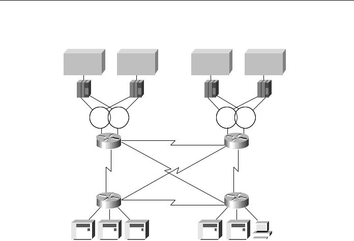
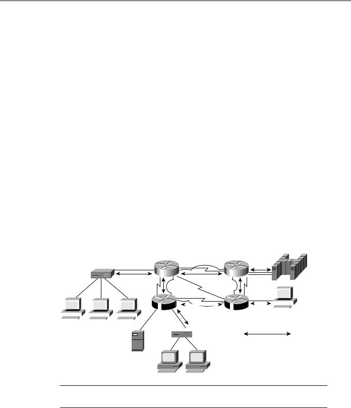
Build a redundant backbone network with routers and high-speed E1 or T1 links in each regional office, as shown in Figure 5-14. Connect multiple SDLC devices to a router via SDLC transport with virtual multidrop. The resulting network increases reliability and minimizes leased-line charges.
Figure 5-14 Connecting multiple SDLC devices via SDLC transport with virtual multidrop.
Main data center |
Disaster recovery center |
||
Host |
Host |
Host |
Host |
3745 |
3745 |
3745 |
3745 |
|
|
T1 |
|
|
Router |
|
Router |
|
|
56 Kbps |
|
|
T1 |
|
56 Kbps |
|
|
T1 |
|
|
Router |
|
Router |
|
|
T1 |
|
|
|
|
|
|
|
|
|
|
|
|
|
|
|
|
|
|
|
|
|
|
|
|
|
|
|
|
|
|
|
|
|
|
|
|
|
|
|
|
|
|
|
|
|
|
|
|
|
|
|
|
|
|
|
|
|
|
|
|
|
|
|
|
|
|
|
|
|
|
|
|
|
|
|
|
|
|
|
|
|
|
|
|
|
|
|
|
|
|
|
|
|
|
|
|
|
|
|
|
|
|
|
|
|
|
|
|
|
|
|
|
|
|
|
|
|
|
|
|
|
|
|
|
|
|
|
|
|
|
|
|
|
|
|
|
|
|
|
|
|
|
|
|
|
|
|
|
|
|
|
|
|
|
|
|
|
|
|
|
|
|
|
|
|
|
|
|
|
|
|
|
|
|
|
|
|
|
|
|
|
|
|
|
|
|
|
|
|
|
|
|
|
|
|
|
|
|
|
|
|
|
|
|
|
|
|
3x74 |
|
|
|
PU 1 |
|
5x94 |
AS400 RS6000 |
OS/2 |
|||||||||||||||||||||||
Phase 2: Fault-Tolerant Host FEP Token Ring and SDLLC Implementation
Implement a fault-tolerant host FEP Token Ring, as shown in Figure 5-15. Connecting existing SDLC devices to the host Token Ring via SDLLC improves response time. Because SDLC devices appear as Token Ring-attached devices to the host, you do not need to regenerate NCP and reload when you are adding or changing PUs and LUs. This can be done dynamically through VTAM-switched major nodes. This implementation also reduces FEP CPU utilization.
Designing SDLC, SDLLC, and QLLC Internetworks 5-21
SDLLC Implementation
Figure 5-15 Fault-tolerant TICs and SDLLC implementation.
Main data center |
Disaster recovery center |
||
Host |
Host |
Host |
Host |
3745 |
3745 |
3745 |
3745 |
Token |
Token |
Token |
Token |
Ring |
Ring |
Ring |
Ring |
|
|
T1 |
|
Router |
Router |
||
|
|
56 Kbps |
|
T1 |
|
|
56 Kbps |
|
|
T1 |
|
Router |
Router |
||
|
|
T1 |
|
|
|
|
|
|
|
|
|
|
|
|
|
|
|
|
|
|
|
|
|
|
|
|
|
|
|
|
|
|
|
|
|
|
|
|
|
|
|
|
|
|
|
|
|
|
|
|
|
|
|
|
|
|
|
|
|
|
|
|
|
|
|
|
|
|
|
|
|
|
|
|
|
|
|
|
|
|
|
|
|
|
|
|
|
|
|
|
|
|
|
|
|
|
|
|
|
|
|
|
|
|
|
|
|
|
|
|
|
|
|
|
|
|
|
|
|
|
|
|
|
|
|
|
|
|
|
|
|
|
|
|
|
|
|
|
|
|
|
|
|
|
|
|
|
|
|
|
|
|
|
|
|
|
|
|
|
|
|
|
|
|
|
|
|
|
|
|
|
|
|
|
|
|
|
|
|
|
|
|
|
|
|
|
|
|
|
|
|
|
|
|
|
|
|
|
|
|
|
|
|
|
|
|
|
|
|
|
|
|
|
|
|
|
|
|
|
|
|
|
|
|
|
|
|
|
|
|
|
|
|
|
|
|
|
|
|
|
|
|
|
3x74 |
PU 1 |
5x94 |
AS400 RS6000 |
|
|
OS/2 |
|||||||||||||||||||||||||
Phase 3: Strategic LAN-to-WAN Implementation
Implement LAN (both Token Ring and Ethernet) internetworks in selected locations along with alternative WAN technologies, such as Frame Relay, as shown in Figure 5-16. Connect LAN-based and remote SDLC devices to host FEP Token Ring via SDLLC, RSRB, and translational bridging, and to host FEP SDLC via reverse SDLLC (SDLC side primary). SNA session integrity is maintained through local termination of both LLC2 and SDLC traffic. These solutions provide needed support of LAN-based applications and improve availability and up time for SNA network devices.
SDLLC Implementation Checklist
Before implementing an SDLLC-based internetwork, make sure you are familiar with the information that deals with SDLC. Depending on your implementation, you might need to review the “SDLLC Configuration” and “SDLLC Implementation Scenarios” sections earlier in this chapter. In general, the following guidelines help you create a working, manageable network:
•
•
•
•
Use a phased approach to implement your router network.
Establish a test environment to initially bring up the routers.
Plan a gradual cutover of end devices into the production environment.
During the cutover period, observe the router’s behavior by using show commands.
5-22 Cisco CCIE Fundamentals: Network Design

SDLLC Implementation Checklist
Figure 5-16 Implementing alternative LAN-to-WAN technologies for an integrated solution.
Main data center |
Disaster recovery center |
Host
3745
Local  acknowledgment
Local acknowledgment
|
|
Host |
Host |
|
|
Host |
|
|
3745 |
|
3745 |
|
3745 |
|
|
Token |
Token |
|
Local |
Token |
Token |
|
|
Ring |
Ring |
|
acknowledgment |
Ring |
Ring |
|
|
|
|
|
T1 |
|
|
|
|
Router |
|
|
Router |
|
|
||
|
|
|
|
|
|
|
Local |
T1 |
|
|
|
|
acknowledgment |
||
|
|
56 Kbps |
|
|
|
||
|
|
Frame Relay |
|
|
|
||
|
|
T1 |
|
|
|
|
|
|
|
|
|
SDLC |
AS/400 Host |
||
|
|
|
|
|
|||
|
|
|
T1 |
|
|
||
|
|
Local |
|
|
|
Local |
|
Router |
|
Router |
|
||||
|
|
acknowledgment |
|||||
acknowledgment |
|
||||||
|
|
|
|
|
|||
|
|
|
|
|
|
||
Token |
Token |
Ring |
Ring |
3274 |
3274 |
AS/400 Host |
|
Strive to create a network that has predictable behavior early in the development cycle. This strategy can prevent problems as more devices are brought online. The following is a specific SDLLC implementation checklist that you can use to identify technologies, implementations, and possible solutions for your internetwork:
Step 1 Evaluate the customer requirements for SDLLC support:
•Identify all host-attached controllers. Examples include 37x5, 3172, and 3174 devices. The host sites might be referred to as local, core, backbone, or data center sites.
•How are the host site controllers connected to the network?
•Is Token Ring already in place? Ethernet?
•What are the link speeds for remote end systems?
•What are the current line utilization measurements? Network Performance Monitor, which makes historical data available, is typically installed in the larger SNA shops.
•What interface type is required (for example: V.24 (EIA/TIA-232, formerly RS-232), V.35, or X.21)?
•What modems, data service units, channel service units, modem-sharing devices or line-sharing devices will be used?
Designing SDLC, SDLLC, and QLLC Internetworks 5-23
QLLC Conversion
•Is Link Problem Determination Aid (LPDA) support required? LPDA is a feature of IBM modems and data service units that reports line quality and statistics to NetView. LPDA Version 1 is not compatible with STUN and SDLLC; LAPD Version 2 may be compatible with STUN.
•What remote end-system types are expected? Examples include 3174, 3274, and AS/400.
•
•
•
Will there be end-system emulation?
What is the current transaction response time? Is subsecond response required?
How many PUs are there? (This information will be important for router utilization sizing.)
•How many LUs are there? (Many busy LUs attached to a PU increases link utilization.)
Step 2 Determine current configuration. Important information includes the following:
•NCP system generation for 3745, 3725, and 3720 devices; in particular, note the LINE, PU, and LU definition statements.
•Local controller current worksheets for 3174 and 3172 devices.
•Remote controller configuration worksheets for 3x74 and 5x94 devices.
•OS/2 Communication Manager configuration files.
•Network topology diagram.
Step 3 Determine the SDLLC features that best suit your requirements.
Confirm that devices to be attached are SDLC PU type 2 devices. Select specific feature requirements, such as local acknowledgment and virtual multidrop.
Step 4 Determine what host conversion changes are required:
•Switched major node definitions for VTAM.
•FEP/NCP changes for Token Ring addition and SDLC link reduction.
QLLC Conversion
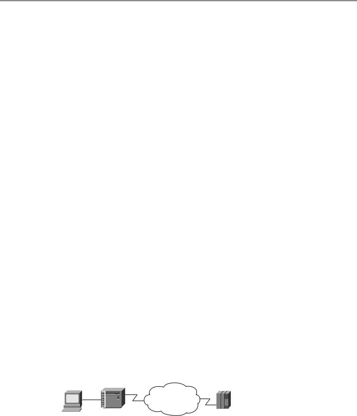
QLLC is a data-link protocol defined by IBM that allows SNA data to be transported across X.25 networks. With QLLC, each SDLC physical link is replaced by a single virtual circuit. Figure 5-17 illustrates a typical QLLC topology. In this topology, both ends of the connection over the X.25 network must be configured for QLLC.
Figure 5-17 Typical QLLC topology.
X.25 network
3174 |
FEP |
QLLC conversion is a feature of Cisco IOS Software Release 10.2 that causes the router to perform all of the translation required to send SNA data over an X.25 network so that IBM devices that are connected to a router do not have to be configured for QLLC.
5-24 Cisco CCIE Fundamentals: Network Design
QLLC Conversion
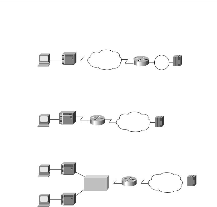
QLLC conversion allows a device (typically a FEP or an AS/400) that is attached either directly to the router or through a Token Ring to communicate with a device (typically a 3174 terminal controller) that is attached to an X.25 network, as shown in Figure 5-18. In this example, only the terminal controller must be configured for QLLC and must have an X.25 interface.
Figure 5-18 Simple topology for QLLC conversion.
X.25 network |
Token |
Router |
Ring |
3174 |
FEP |
In some topologies, one router interface uses SDLC to communicate with the terminal controller, and another router interface uses X.25 to communicate with the remote device over the X.25 network. In Figure 5-19, the router, configured for QLLC conversion, handles SNA traffic between the terminal controller and the FEP.
Figure 5-19 Topology that uses SDLC and QLLC conversion.
X.25 network
3174
FEP
QLLC conversion also supports multiple SDLC connections coming through an MSD, as shown in Figure 5-20.
Figure 5-20 QLLC conversion supports multidrop SDLC topology.
3174
MSD |
Router |
X.25 network |
|
FEP
3174
The router that is configured for QLLC conversion does not need to be on the same Token Ring as the FEP. In Figure 5-21, Router A is configured for QLLC and remote source-route bridging (RSRB), and Router B is configured for RSRB only. RSRB allows the FEP to connect to Router A. If a Token Ring connected to the X.25 network communicates with the Token Ring attached to the FEP by a protocol other than SRB, RSRB can provide connectivity.
Designing SDLC, SDLLC, and QLLC Internetworks 5-25
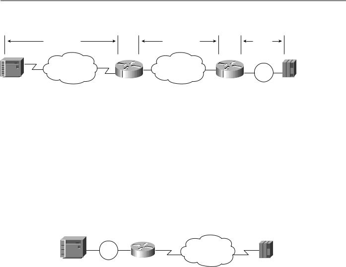
Summary
Figure 5-21 |
Comples QLLC conversion topology. |
|
|
QLLC session |
TCP session |
|
LLC2 |
|
|
|
session |
X.25 network |
IP network |
|
Token |
|
Router A |
Router A |
Ring |
3174 |
|
|
FEP |
Figure 5-21 shows an example using local acknowledgment, which causes the LLC2 session from the Token Ring-attached SNA device (the FEP) to be terminated at the adjacent router (Router B). A TCP session transports the data from Router B to the router attached to the X.25 network (Router A). Only Router A is configured for QLLC conversion. When enabled, local acknowledgment applies to all QLLC connections. The source-bridge qllc-local-ack global configuration command enables local acknowledgment and applies to all QLLC connections.
In pass-through mode, local acknowledgment is not used. Instead, the LLC2 session from the Token Ring-attached SNA device (the FEP) is terminated at the router connected to the X.25 network (Router A).
QLLC conversion also supports a configuration in which SNA end stations (3174 or equivalent) that are connected to a Token Ring reach the FEP through an X.25 connection, as shown in Figure 5-22. In this case, IBM Network Packet Switching Interface (NPSI) software is installed on the FEP.
Figure 5-22 QLLC conversion supports SNA end-station connections over Token Ring and X.25 networks.
Token |
|
X.25 network |
|
Ring |
Router |
||
|
|||
3174 |
|
FEP |
Summary
This chapter addresses some of the special requirements for implementing routing technology within IBM System Network Architecture (SNA) environments. It describes the three techniques designed to enable internetworking capabilities for SNA-based network architectures, as follows:
•
•
•
SDLC via STUN
SDLLC Implementation
QLLC Conversion
5-26 Cisco CCIE Fundamentals: Network Design

C H A P T E R 6
Designing APPN Internetworks
Advanced peer-to-peer networking (APPN) is a second generation of the Systems Network Architecture (SNA) from IBM. It moves SNA from a hierarchical, mainframe-centric environment to a peer-to-peer environment. It provides capabilities similar to other LAN protocols, such as dynamic resource definition and route discovery.
This chapter focuses on developing the network design and planning a successful migration to APPN. It covers the following topics:
•
•
•
•
•
•
•
•
•
Evolution of SNA
When to Use APPN as Part of a Network Design
When to Use APPN Versus Alternative Methods of SNA Transport
Overview of APPN
Scalability Issues
Backup Techniques in an APPN Network
APPN in a Multiprotocol Environment
Network Management
Configuration Examples
Note Although this chapter does discuss using APPN with DLSw+, for detailed information on using DLSw+, refer to Chapter 7, “Designing DLSw+ Internetworks.”
Evolution of SNA
Introduced in 1974, subarea SNA made the mainframe computer running Advanced Communications Function/Virtual Telecommunication Access Method (ACF/VTAM) the hub of the network. The mainframe was responsible for establishing all sessions (a connection between two resources over which data can be sent), activating resources, and deactivating resources. The design point of subarea SNA was reliable delivery of information across low-speed analog lines. Resources were explicitly predefined. This eliminated the need for broadcast traffic and minimized header overhead.
Many enterprises today maintain two networks: a traditional, hierarchical SNA subarea network and an interconnected LAN network that is based on connectionless, dynamic protocols. The advantage of the subarea SNA network is that it is manageable and provides predictable response time. The disadvantages are that it requires extensive system definition and does not take advantage of the capabilities of intelligent devices (for example, the PCs and workstations).
Designing APPN Internetworks 6-1
Evolution of SNA
Role of APPN
With APPN, you can consolidate the two networks (an SNA subarea network and an interconnected LAN network) because APPN has many of the characteristics of the LAN networks and still offers the advantages of an SNA network. The major benefits of using APPN include the following:
•Connections are peer-to-peer, allowing any end user to initiate a connection with any other end user without the mainframe (VTAM) involvement.
•APPN supports subarea applications as well as newer peer-to-peer applications over a single network.
•APPN provides an effective routing protocol to allow SNA traffic to flow natively and concurrently with other protocols in a single network.
•Traditional SNA class of service (COS)/transmission priority can be maintained.
As SNA has evolved, one feature has remained critical to many users: COS. This feature provides traffic prioritization on an SNA session basis on the backbone. This, in turn, allows a single user to have sessions with multiple applications, each with a different COS. In APPN, this feature offers more granularity and extends this capability all the way to the end node rather than just between communication controllers.
Types of APPN Nodes
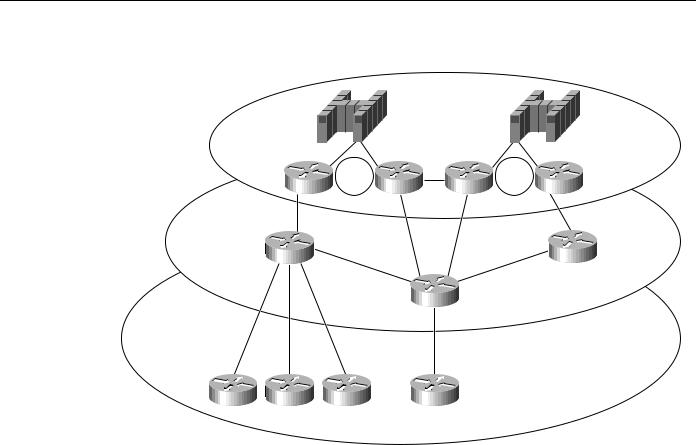
An APPN network has three types of nodes: LEN nodes, end nodes (EN), and network nodes (NN), as shown in Figure 6-1.
Figure 6-1 Different types of APPN nodes.
NN
NN |
NN |
EN
APPN
|
|
|
|
|
|
|
|
|
|
|
|
|
|
|
|
|
|
|
|
|
|
|
|
|
|
|
|
|
|
|
|
|
|
|
|
|
|
|
|
|
|
|
|
|
|
|
|
|
|
|
|
|
|
|
|
|
|
|
|
|
|
|
|
|
|
|
|
|
|
|
|
|
|
|
|
|
|
|
|
|
|
|
|
|
|
|
|
|
|
|
|
|
|
|
|
|
|
|
|
|
|
|
|
|
|
|
|
EN |
|||
|
|
|
|
|
|
|
|
|
|
|
|
|
|
|
NN |
|
|
NN |
|
||||||||
|
|
|
|
|
|
|
|
|
|
|
|
|
|
|
|||||||||||||
|
|
|
|
|
|
|
|
|
|
|
|
|
|
|
|
|
|
|
|
|
|
|
|
|
|
|
|
 EN
EN
CP-CP session pair
LEN node
EN = end node
NN = network node
Note Throughout the rest of this chapter, the abbreviations EN and NN are used in the illustrations. The full terms (end node and network node) are used within the text for clarity.
Table 6-1 describes these different types of APPN nodes. The control point (CP), which is responsible for managing a node’s resources and adjacent node communication in APPN, is key to an APPN node. The APPN Control Point is the APPN equivalent of the SSCP.
6-2 Cisco CCIE Fundamentals: Network Design

|
|
|
When to Use APPN as Part of a Network Design |
|
Table 6-1 |
Different Types of APPN Nodes |
|
|
|
|
|
|
Type of APPN Node |
Description |
|
|
|
|
|
|
Local Entry Networking |
LEN nodes are pre-APPN, peer-to-peer nodes. They can participate in an APPN network |
|
|
(LEN) nodes |
|
by using the services provided by an adjacent network node. The CP of the LEN node |
|
|
|
manages the local resources but does not establish a CP-CP session with the adjacent |
|
|
|
network node. Session partners must be predefined to the LEN node, and the LEN node |
|
|
|
must be predefined to the adjacent network node. LEN nodes are also referred to as SNA |
|
|
|
node type 2.1, physical unit (PU) type 2.1, or PU2.1. |
|
|
|
|
|
End nodes |
|
End nodes contain a subset of full APPN functionality. They access the network through |
|
|
|
an adjacent network node and use the adjacent network node’s routing services. An end |
|
|
|
node establishes a CP-CP session with an adjacent network node, and then uses that |
|
|
|
session to register resources, request directory services, and request routing information. |
|
|
|
|
|
Network nodes |
|
Network nodes contain full APPN functionality. The CP in a network node is responsible |
|
|
|
for managing the resources of the network node along with the attached end nodes and |
LEN nodes. The CP establishes CP-CP sessions with adjacent end nodes and network nodes. It also maintains network topology and directory databases, which are created and updated by dynamically gathering information from adjacent network nodes and end nodes over CP-CP sessions. In an APPN environment, network nodes are connected by transmission groups (TGs), which in the current APPN architecture refers to a single link. Consequently, the network topology is a combination of network nodes and transmission groups.
For more background information on APPN, refer to the section “Overview of APPN” later in this chapter.
When to Use APPN as Part of a Network Design
APPN has two key advantages over other protocols:
•
•
Native SNA routing
COS for guaranteed service delivery
APPN, like Transmission Control Protocol/Internet Protocol (TCP/IP), is a routable protocol in which routing decisions are made at the network nodes. Although only the network node adjacent to the originator of the session selects the session path, every network node contributes to the process by keeping every other network node informed about the network topology. The network node adjacent to the destination also participates by providing detailed information about the destination. Only routers that are running as APPN network nodes can make routing decisions.
You need APPN in your network when a routing decision (for example, which data center or path) must be made. Figure 6-2 helps to illustrate the criteria you use to determine where APPN should be used in a network.
Designing APPN Internetworks 6-3
When to Use APPN as Part of a Network Design
Figure 6-2 Determining where to use APPN in a network.
Data center
Token |
Token |
Ring |
Ring |
Backbone
Branch
In Figure 6-2, a single link connects the branch office to the backbone. Therefore, a routing decision does not need to be made at the branch office. Consequently, an APPN network node might not be necessary at those sites.
Because there are two data centers, however, the routing decision about which data center to send the message to must be made. This routing decision can be made either at the data center or at the backbone routers. If you want this routing decision made at the data center, all messages are sent to a single data center using DLSw+, for example, and then routed to the correct data center using APPN only in the routers in the data center. If you want the routing decision to be made at the backbone routers, place the APPN network node in the backbone routers, where alternative paths are available for routing decisions outside of the data center. In this example, this latter approach is preferred because it isolates the function at the data centers routers to channel attachment, reduces the number of hops to the second data center, and provides a path to a backup data center if something catastrophic occurs.
Because APPN requires more memory and additional software, it is generally a more expensive solution. The advantages of direct APPN routing and COS, however, often offset the added expense. In this case, the added expense to add APPN to the backbone and data center routers might be justifiable, whereas added expense at the branch might not be justifiable.
APPN at Every Branch
There are two cases for which adding an APPN network node at every branch can be cost justified:
•
•
When COS Is Required
When Branch-to-Branch Routing Is Required
6-4 Cisco CCIE Fundamentals: Network Design