
Cisco. Fundamentals Network Design - Cisco Press
.pdf
APPN at Every Branch
When COS Is Required
COS implies that the user accesses multiple applications and must be able to prioritize traffic at an application level. Although other priority schemes, such as custom queuing, might be able to prioritize by end user, they cannot prioritize between applications for an individual user. If this capability is critical, APPN network nodes must be placed in the individual branches to consolidate the traffic between multiple users using COS. For instance, COS can ensure that credit card verification always gets priority over batch receipts to a retail company’s central site.
It is important to understand where COS is used in the network today. If the network is a subarea SNA network, COS is used only between front-end processors (FEPs) and ACF/VTAM on the mainframe. Unless there is already an FEP at the branch office, they do not have traffic prioritization from the branch, although traffic can be prioritized from the FEP out. In this case, adding an APPN network node at the branch office would prioritize the traffic destined for the data center sooner rather than waiting until it reaches the FEP—adding function over what is available today.
When Branch-to-Branch Routing Is Required
If branch-to-branch traffic is required, you can send all traffic to the central site and let those APPN network nodes route to the appropriate branch office. This is the obvious solution when both data center and branch-to-branch traffic are required and the branch is connected to the backbone over a single link. However, if a separate direct link to another branch is cost-justifiable, routing all traffic to the data center is unacceptable. In this case, making the routing decision at the branch is necessary. Using an APPN network node at the branch, data center traffic is sent over the data center link and branch-to-branch traffic is sent over the direct link.
In the example in Figure 6-3, each branch has two links to alternative routers at the data center. This is a case where APPN network nodes might be required at the branches so that the appropriate link can be selected. This can also be the design for branch-to-branch routing, adding a single hop rather than creating a full mesh of lines. This provides more direct routing than sending everything through the data center.
Designing APPN Internetworks 6-5
When to Use APPN Versus Alternative Methods of SNA Transport
Figure 6-3 Sample network for which branch-to-branch routing is required.
Data center
Token |
Token |
Ring |
Ring |
Backbone
Branch
As you also learn in this chapter, scalability issues make it advantageous to keep the number of network nodes as small as possible. Understanding where native routing and COS is needed is key in minimizing the number of network nodes.
In summary, choosing where to implement APPN must be decided based on cost, scalability, and where native routing and COS are needed. Implementing APPN everywhere in your network might seem to be an obvious solution, even when not necessary. It must be understood, however, that if you were to deploy APPN everywhere in your network it probably would be a more costly solution than necessary and may potentially lead to scalability problems. Consequently, the best solution is to deploy APPN only where it is truly needed in your network.
When to Use APPN Versus Alternative Methods of SNA Transport
APPN and boundary network node (BNN)/boundary access node (BAN) over Frame Relay using RFC 1490 are the two methods of native SNA transport, where SNA is not encapsulated in another protocol. BAN and BNN allow direct connection to an FEP, using the Frame Relay network to switch messages, rather than providing direct SNA routing.
Although native might seem to be the appropriate strategy, APPN comes at the price of cost and network scalability, as indicated in the preceding section. With BNN/BAN additional cost is required to provide multiprotocol networking because the FEP does not handle multiple protocols. This implies that additional routers are required in the data center for other protocols and separate virtual circuits are required to guarantee service delivery for the SNA or APPN traffic.
DLSw+ provides encapsulation of SNA, where the entire APPN message is carried as data inside a TCP/IP message. There is often concern about the extra 40 bytes of header associated with TCP/IP. However, because Cisco offers alternatives such as Data Link Switching Lite, Fast Sequenced Transport (FST), and Direct Transport, which have shorter headers, header length is deemed noncritical to this discussion.
6-6 Cisco CCIE Fundamentals: Network Design

Overview of APPN
DLSw+ is attractive for those networks in which the end stations and data center will remain SNA-centric, but the backbone will be TCP/IP. This allows a single protocol across the backbone, while maintaining access to all SNA applications. DLSw+ does not provide native APPN routing, nor does it provide native COS. Consequently, DLSw+ is preferable for networks, in which cost is a key criterion, that have the following characteristics:
•
•
A single data center or mainframe
Single links from the branches
In general, DLSw+ is a lower-cost solution that requires less memory and software. In the vast majority of networks, DLSw+ will be combined with APPN—using APPN only where routing decisions are critical. With TCP/IP encapsulation, the TCP layer provides the same reliable delivery as SNA/APPN, but does not provide the native routing and COS.
TN3270 transports 3270 data stream inside a TCP/IP packet without SNA headers. Therefore, this solution assumes that the end station has only a TCP/IP protocol stack and no SNA. Therefore, TN3270 is not an alternative to APPN because APPN assumes the end station has an SNA protocol stack. APPN, like DLSw+, may still be required in the network to route between TN3270 servers and multiple mainframes or data centers.
In summary, APPN will frequently be used with DLSw+ in networks when a single backbone protocol is desired. BAN/BNN provides direct connectivity to the FEP but lacks the multiprotocol capabilities of other solutions. TN3270 is used only for TCP/IP end stations.
Overview of APPN
This section provides an overview of APPN and covers the following topics:
•
•
•
•
Defining Nodes
Establishing APPN Sessions
Understanding Intermediate Session Routing
Using Dependent Logical Unit Requester/Server
Defining Nodes
Nodes, such as ACF/VTAM, OS/400 and Communications Server/2 (CS/2), can be defined as either network nodes or end nodes.When you have a choice, consider the following issues:
•Network size—How large is the network? Building large APPN networks can introduce scalability issues. Reducing the number of network nodes is one solution for avoiding scalability problems. For more information on reducing the number of network nodes, see the section “Reducing the Number of Network Nodes” later in this chapter.
•Role of the node—Is it preferable to have this node performing routing functions as well as application processing? A separate network node can reduce processing cycles and memory requirements in an application processor.
Generally, you should define a network node whenever a routing decision needs to be made.
Designing APPN Internetworks 6-7

Overview of APPN
APPN Node Identifiers
An APPN node is identified by its network-qualified CP name, which has the format netid.name. The network identifier (netid) is an eight-character name that identifies the network or subnetwork in which the resource is located. The network identifier and name must be a combination of uppercase letters (A through Z), digits (0 through 9), and special characters ($,#,or @) but cannot have a digit as the first character.
Establishing APPN Sessions
In order for an APPN session to be established, the following must occur:
1The end user requests a session with an application, which causes the end node to begin the process of session establishment by sending a LOCATE message to its network node server. For session initiation, the network node server provides the path to the destination end node, which allows the originating end node to send messages directly to the destination.
2The network node uses directory services to locate the destination by first checking its internal directories. If the destination is not included in the internal directory, the network node sends a LOCATE request to the central directory server if one is available. If a central directory server is not available, the network node sends a LOCATE broadcast to the adjacent network nodes that in turn propagate the LOCATE throughout the network. The network node server of the destination returns a reply that indicates the location of the destination.
3Based on the location of the destination, the COS requested by the originator of the session, the topology database, and the COS tables, the network node server of the originator selects the least expensive path that provides the appropriate level of service.
4The originating network node server sends a LOCATE reply to the originating end node. The LOCATE reply provides the path to the destination.
5The originating end node is then responsible for initiating the session. A BIND is sent from the originating end node to the destination end node, requesting a session. After the destination replies to the BIND, session traffic can flow.
Understanding Intermediate Session Routing
Session connectors are used in place of routing tables in APPN. The unique session identifier and port from one side of the node are mapped to the unique session identifier and port on the other side. As data traffic passes through the node, the unique session identifier in the header is swapped for the outgoing identifier and sent out on the appropriate port, as shown in Figure 6-4.
Figure 6-4 Intermediate session routing label swap.
|
Session |
|
Session |
|||
|
connector |
|
connector |
|||
|
SID |
SID |
|
SID |
SID |
|
|
245 |
321 |
|
321 |
548 |
|
|
|
|
|
|
|
|
|
|
|
|
|||
|
NN 1 |
|
NN 4 |
|
||
EN A |
|
|
|
|
|
EN B |
|
|
|
|
|
|
|
SID 245 |
SID 321 |
|
SID 548 |
|||
Session Stage 1 |
Session Stage 2 |
Session Stage 3 |
||||
6-8 Cisco CCIE Fundamentals: Network Design

Using Dependent Logical Unit Requester/Server
This routing algorithm is called intermediate session routing (ISR). It supports dynamic route definition and incorporates the following legacy features:
•Node-to-node error and flow control processing —This reflects the 1970s method of packet switching in which many line errors dictated error and flow control at each node. Given the current high-quality digital facilities in many locations, this redundant processing is unnecessary and significantly reduces end-to-end throughput. End-to-end processing provides better performance and still delivers the necessary reliability.
•Disruptive session switching around network failures—Whenever a network outage occurs, all sessions using the path fail and have to be restarted to use an alternative path.
Because these features are undesirable in most high-speed networks today, a newer routing algorithm—High Performance Routing (HPR)—has been added to APPN that supports nondisruptive rerouting around failures and end-to-end error control, flow control, and segmentation. Cisco routers support both ISR and HPR.
Using Dependent Logical Unit Requester/Server
Dependent Logical Unit Requester/Server (DLUR/DLUS) is an APPN feature that allows legacy traffic to flow on an APPN network. Prior to the introduction of this feature, the APPN architecture assumed that all nodes in a network could initiate peer-to-peer traffic (for example, sending the BIND to start the session). Many legacy terminals that are referred to as Dependent Logical Units (DLUs) cannot do this and require VTAM to notify the application, which then sends the BIND.
Getting the legacy sessions initiated requires a client-server relationship between ACF/VTAM (Dependent LU server—DLUS) and the Cisco router (Dependent LU Requester—DLUR). A pair of logical unit (LU) type 6.2 sessions are established between the DLUR and DLUS—one session is established by each end point. These sessions are used to transport the legacy control messages that must flow to activate the legacy resources and initiate their logical unit to logical unit (LU-LU) sessions. An LU-LU session is the connection that is formed when the five steps described earlier in the section “Establishing APPN Sessions” are completed.
For example, an activate logical unit (ACTLU) message must be sent to the LU to activate a legacy LU. Because this message is not recognized in an APPN environment, it is carried as encapsulated data on the LU 6.2 session. DLUR then deencapsulates it, and passes it to the legacy LU. Likewise, the DLU session request is passed to the ACF/VTAM DLUS, where it is processed as legacy traffic. DLUS then sends a message to the application host, which is responsible for sending the BIND.
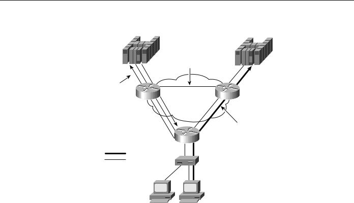
After the legacy LU-LU session is established, the legacy data flows natively with the APPN traffic, as shown in Figure 6-5.
Designing APPN Internetworks 6-9
Cisco Implementation of APPN
Figure 6-5 DLU session processing.
VTAM notifies |
Application |
host |
|
application host |
|
DLUS |
|
Session establishment:
LU 6.2 "pipes"
APPN network
Session data
DLUR
Session data
LU 6.2 pipes
Dependent LUs
Cisco Implementation of APPN
This section provides an overview of Cisco’s implementation of APPN and discusses where APPN resides in the Cisco IOS software. Cisco licensed the APPN source code from IBM and then ported it to the Cisco IOS software using network services from the data-link controls (DLCs).
Applications use APPN to provide network transport. APPN runs on top of the Cisco IOS software. APPN is a higher-layer protocol stack that requires network services from DLC. Cisco’s APPN implementation is compliant with the APPN Architecture of record. When used with other features in the Cisco IOS software, APPN provides the following unique features:
•APPN can use DLSw+ or RSRB as a network transport, thereby supporting APPN over a native TCP/IP network.
•APPN can be used with downstream physical unit concentration (DSPU) to reduce the number of downstream PUs visible to VTAM. This reduces VTAM definition and network restart times.
•In addition to COS, priority queuing, custom queuing, and weighted fair queuing can be used with COS to ensure traffic prioritization and/or bandwidth reservation between protocols.
•Network management options are supported that include native SNA management services using Native Service Point (NSP) in the Cisco router, and Simple Network Management Protocol (SNMP) management using CiscoWorks Blue applications.
•Using Channel Interface Processor (CIP) or Channel Port Adapter (CPA), the Cisco APPN network node can interface directly with ACF/VTAM across the channel. VTAM can be defined either as an end node or network node.
6-10 Cisco CCIE Fundamentals: Network Design

Scalability Issues
Scalability Issues
As a single-network link state architecture, the network topology is updated as changes occur. This results in significant network traffic if instability occurs, and significant memory and processing to maintain the large topology databases and COS tables. Similarly, in large networks, dynamic discovery of resources can consume significant bandwidth and processing. For these reasons, scalability becomes a concern as network size increases. The number of nodes that are too large depends on the following:
•Amount of traffic
•Network stability
•The number of the techniques, which are described in this section, that are being used to control traffic and processing
Essentially, to allow growth of APPN networks, the network design must focus on reducing the number of topology database updates (TDUs) and LOCATE search requests.
Topology Database Update Reduction
APPN is a link-state protocol. Like other link-state-based algorithms, it maintains a database of the entire topology information of the network. Every APPN network node in the network sends out TDU packets that describe the current state of all its links to its adjacent network nodes. The TDU contains information that identifies the following:
•
•
•
The characteristics of the sending node
The node and link characteristics of the various resources in the network
The sequence number of the most recent update for each described resource
A network node that receives a TDU packet propagates this information to its adjacent network nodes using a flow reduction technique. Each APPN network node maintains full knowledge of the network and how the network is interconnected. Once a network node detects a change to the network (either a change to the link, or the node), it floods TDUs throughout the network to ensure rapid convergence. If there is an unstable link in the network, it can potentially cause many TDU flows in a network.
As the number of network nodes and links increases, so does the number of TDU flows in your network. This type of distributing topology can consume significant CPU cycles, memory, and bandwidth. Maintaining routes and a large, complete topology subnet can require a significant amount of dynamic memory.
You can use the following techniques to reduce the amount of TDU flows in the network:
•
•
•
Reduce the number of links
Reduce the number of CP-CP sessions
Reduce the number of network nodes in the network
Reducing the Number of Links
The first technique for reducing the amount of TDU flows in the network is to reduce the number of links in your network. In some configurations, it might be possible to use the concept of connection network to reduce the number of predefined links in your network. Because network nodes exchange information about their links, the fewer links you define, the fewer TDU flows can occur.
Designing APPN Internetworks 6-11
Scalability Issues
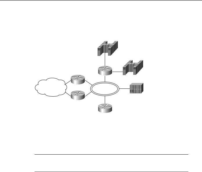
Figure 6-6 shows the physical view of an APPN network. In this network NN1, NN2, and NN3 are routers attached to an FDDI LAN.
Figure 6-6 Physical view of an APPN network.
NNS
EN1
CIP
NN1
EN2
WAN |
FDDI Ring |
NN2
NN3
The network-node server (NNS), EN1, and EN2 hosts are attached to the same FDDI LAN via a CIP router or a cluster controller. These nodes on the FDDI LAN have any-to-any connectivity. To reflect any-to-any connectivity in APPN, NN1 needs to define a link to NN2, NN3, NNS (VTAM host), EN1 (VTAM data host), and EN2 (EN data host). The transmission groups connecting network nodes are contained in the network topology database. For every link that is defined to the network node, TDUs are broadcast.
Note Throughout the rest of this chapter, the abbreviation NNS is used in the illustrations. When the text refers to an NNS icon in an illustration, the abbreviation is also used; otherwise, the full term (network-node server) is used within the text for clarity.
Figure 6-7 shows the logical view of the APPN network, shown earlier in Figure 6-6. When NN1 first joins the network, NN1 activates the links to NN2, NN3, NNS, EN1, and EN2. CP-CP sessions are established with the adjacent network nodes. Each adjacent network node sends a copy of the current topology database to NN1. Similarly, NN1 creates a TDU about itself and its links to other network nodes and sends this information over the CP-CP sessions to NN2, NN3 and NNS. When NN2 receives the TDU from NN1, it forwards the TDU to its adjacent network nodes, which are NN3 and NNS. Similarly, NN3 and NNS receive the TDU from NN1 and broadcast this TDU to their adjacent network nodes. The result is that multiple copies of the TDU are received by every network node.
6-12 Cisco CCIE Fundamentals: Network Design
Topology Database Update Reduction
Figure 6-7 Logical view of an APPN network without connection network deployed.
NNS
NN1 |
EN1 |
NN2 |
EN2 |
NN3
The transmission groups that connect the end nodes are not contained in the network topology database. Consequently, no TDUs are broadcast for the two links to EN1 and EN2. If the number of transmission groups connecting network nodes can be reduced, the number of TDU flows can also be reduced.
By using the concept of connection networks, you can eliminate the transmission group definitions, and therefore reduce TDU flows. A connection network is a single virtual routing node (VRN), which provides any-to-any connectivity for any of its attached nodes. The VRN is not a physical node, it is a logical entity that indicates that nodes are using a connection network and a direct routing path can be selected.
Figure 6-8 shows the APPN network shown in Figure 6-6 with connection network deployed.
Figure 6-8 Logical view of an APPN network with connection network deployed.
NNS
EN1
NN1
VRN
EN2
NN2 |
|
|
|
NN3 |
|
|
|
|
|
|
|
NN1, NN2, and NN3 define a link to the network-node server (NNS) and a link to the VRN. When the link between NN1 and NNS is activated, NNS sends a copy of the current network topology database to NN1. NN1 creates a TDU about itself, its link to NNS, and its link to the VRN. It then sends this information to NNS. NN1 does not have a link defined to NN2 and NN3, therefore, there are no TDUs sent to NN2 and NN3 from NN1. When NNS receives the TDU information from NN1, NNS forwards it to NN2 and NN3. Neither NN2 nor NN3 forwards the TDU information because they only have a connection to NNS. This significantly reduces the number of TDU flows in the network.
When a session is activated between resources on the connection network, the network-node server recognizes that this is a connection network and selects a direct route rather than routing through its own network nodes. Cisco recommends that you apply the concept of connection networks whenever possible. Not only does it reduce the number of TDU flows in the network, it also greatly reduces system definitions.
As shown in the example, a LAN (Ethernet, Token Ring, or FDDI) can be defined as a connection network. With ATM LAN Emulation (LANE) services, you can interconnect ATM networks with traditional LANs. From APPN’s perspective, because an ATM-emulated LAN is just another LAN, connection network can be applied. In addition to LANs, the concept of connection networks can
Designing APPN Internetworks 6-13
Scalability Issues
apply to X.25, Frame Relay, and ATM networks. It should also be noted that technologies such as RSRB and DLSw appear as LANs to APPN. You can also use connection network in these environments. APPN, in conjunction with DLSw+ or RSRB, provides a synergy between routing and bridging for SNA traffic.
Reducing the Number of CP-CP Sessions
The second technique for reducing the amount of TDU flows in the network is to reduce the number of CP-CP sessions in your network. Network nodes exchange topology updates over CP-CP sessions. The number of CP-CP sessions has a direct impact on the number of TDU flows in the network.
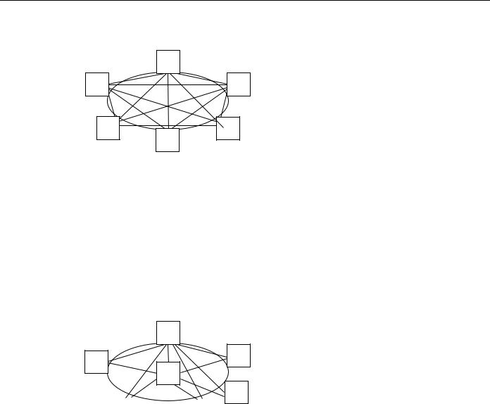
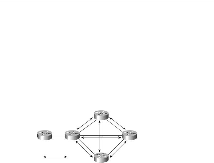
For example, in Figure 6-9, NN2, NN3, NN4, and NN5 are in a fully meshed network. Every network node establishes CP-CP sessions with its adjacent network nodes. This means that NN2 establishes CP-CP sessions with NN3, NN4, and NN5. NN3 establishes CP-CP sessions with NN2, NN4, NN5, and so forth.
Figure 6-9 Fully meshed CP-CP sessions.
|
|
NN3 |
NN1 |
NN2 |
NN4 |
CP-CP sessions
NN5
If the link fails between NN1 and NN2, TDU updates are broadcast from NN2 to NN3, NN4, and NN5. When NN3 receives the TDU update, it resends this information to NN4 and NN5. Similarly, when NN5 receives the TDU update, it resends this information to NN3 and NN4. This means that NN4 receives the same information three times. It is recommended that the number of CP-CP sessions are kept to a minimum so that duplicate TDU information will not be received.
In Figure 6-10, CP-CP sessions exist only between NN2 and NN3, NN2 and NN4, and NN2 and NN5; no other CP-CP sessions exist. When the link fails between NN1 and NN2, NN2 broadcasts transmission group updates to NN3, NN4, and NN5. None of the three NNs forwards this information to the rest of the network because CP-CP sessions do not exist. Although this minimizes the TDU flows, if the link between NN2 and NN3 fails, this becomes a disjointed APPN network and NN3 is isolated.
6-14 Cisco CCIE Fundamentals: Network Design
