

Cisco. Fundamentals Network Design - Cisco Press
.pdfWAN Framing
even in the presence of SRB framing. IPX stations can be linked via SRB networks or locally connected to a Token Ring with SRB framing. A router will route to the IPX station by first searching for the station and then framing each Token Ring frame with RII and a RIF.
The second benefit of multiring is that all outgoing packets for a specific routable protocol are framed in an SRB frame. The router creates a valid SRB frame by transmitting an explorer packet to create a valid RIF entry for the SRB frame of a routable network packet.
The third benefit of multiring is that it allows a smooth transition from a previously framed SRB network to a routed network. For example, a locally connected Token Ring can either use an IPX frame or an SRB frame depending on what is currently in use. To leverage existing IPX servers with SRB drivers, configure the multiring for that specific Token Ring. A typical multiring interface configuration example might be as follows:
interface tokenring 0 source-bridge 10 1 100 multiring ipx spanning
WAN Framing
Routers recognize two forms of SRB. The first is local SRB, which is characterized by either the standard single ring-to-bridge-to-ring combination, or a flexible form using a multiple ring-to-bridge-to-virtual ring arrangement. The second form of SRB involves WAN connections and is called remote SRB (RSRB).
The framing that occurs to support WAN activities is twofold. First, the SRB frame is encapsulated in one of three ways: Transmission Control Protocol/Internet Protocol (TCP/IP) encapsulation, Fast Sequence Transport (FST) encapsulation, or direct High-Level Data Link Control (HDLC) encapsulation. Next, the frame is placed in the WAN frame for the appropriate WAN media, such as HDLC, Frame Relay, or Switched Multimegabit Data Service (SMDS).
If you select direct encapsulation for a WAN serial link, you avoid the overhead of encapsulating into either IP or TCP. The datagram is framed directly into HDLC. Direct encapsulation for WAN frames works only for HDLC. Over a multiaccess media, such as Ethernet or Fiber Distributed Data Interface (FDDI), direct encapsulation can be used to transmit data from one router to another.
Selection of encapsulation is critical to the performance of the underlying network and affects the degree to which the topology can scale to very large networks of token rings. Each encapsulation form is addressed in the following sections.
TCP/IP Encapsulation
TCP/IP encapsulation is the most common encapsulation format. Figure 4-18 illustrates a TCP/IP-encapsulated SRB frame. The chief benefit of TCP/IP encapsulation is a robust set of capabilities that ensures reliable transport.
Figure 4-18 SRB frame encapsulated in TCP/IP with HDLC header.
|
|
4 |
|
|
|
|
48 bytes |
|
|
|
|
16 |
|
|
|
|
|
bytes |
|
|
|
|
|
|
bytes |
|
|||||
|
|
|
|
|
|
|
|
|
|
||||||
|
|
|
|
|
|
|
|
|
|
|
|
|
|
|
|
|
|
|
|
|
|
|
|
|
|
|
|
|
|
|
|
|
HDLC |
|
|
TCP/IP |
|
Cisco |
SRB frame |
||||||||
|
|
|
|
virtual |
|||||||||||
|
header |
|
|
header |
|
||||||||||
|
|
|
|
|
ring |
|
|||||||||
|
|
|
|
|
|
|
|
|
|
|
|
|
|||
|
|
|
|
|
|
|
|
|
|
|
|
|
|
|
|
Designing SRB Internetworks 4-19

SRB Technology Overview and Implementation Issues
Because many tasks are involved in TCP/IP encapsulation, such as packet reordering, running timers for retransmission, and sending acknowledgments, TCP/IP encapsulation is costly in terms of CPU overhead. For both LANs and WANs, TCP/IP encapsulation incurs additional CPU overhead because all framing occurs in the CPU and the resulting IP frame is then process switched, which incurs additional overhead. (Process switching and its associated costs are discussed in “Process Switching” later in this chapter.)
Because of the high overhead associated with TCP/IP encapsulation, there is a significant upper boundary to maximum traffic forwarding. Performance is not the only constraint for using TCP/IP; fewer connections to other SRB rings can be supported using TCP/IP than any other encapsulation because of the processor overhead required to maintain the TCP structure. In general, you should limit the maximum number of remote peers connected to a single Cisco CSC/4 or RP card using TCP/IP encapsulation. Issues that can affect the acceptable number of remote peers include link speed, traffic load, number of supported protocols, routing platform implemented, and the level of other non-SRB activity occurring in the router.
Fast Sequenced Transport (FST) Encapsulation
Fast Sequenced Transport (FST) encapsulation is an alternative to TCP/IP encapsulation. FST encapsulation creates an IP frame with a sequence number; this frame is transmitted to an IP destination. At arrival, FST encapsulation strips the IP frame. If the sequence number of the arriving frame is greater than the sequence number of the last frame that arrived, FST encapsulation places the frame on the destination ring. If the sequence number of the arriving frame is less than the last frame transmitted by FST encapsulation, the frame is discarded, and the router relies on the transport mechanism of LLC2 to request the discarded or out-of-order frames to be retransmitted.
FST encapsulation is configured on a per-remote-ring basis. A typical example of using the fst keyword with the source-bridge remote-peer global configuration command follows:
source-bridge remote-peer 10 fst 131.108.3.2
The benefit of FST encapsulation is sustained end-to-end performance across multiple hops. FST is fast because the IP encapsulation happens on the interface card (AGS+, Cisco 7000, MGS, and CGS) or the system memory (IGS, Cisco 2000, Cisco 2500, Cisco 3000, and Cisco 4000) while the processor is in interrupt mode. For WAN transmissions, once the framing occurs, you can select an IP switching mechanism, either process switching or fast switching, depending on the result you want. Figure 4-19 illustrates the frame format of FST encapsulation.
Figure 4-19 SRB frame encapsulated in FST with HDLC header.
|
|
4 |
|
|
|
|
20 bytes |
|
|
|
|
16 |
|
|
|
|
|
bytes |
|
|
|
|
|
|
bytes |
|
|||||
|
|
|
|
|
|
|
|
|
|
||||||
|
|
|
|
|
|
|
|
|
|
|
|
|
|
|
|
|
|
|
|
|
|
|
|
|
|
|
|
|
|
|
|
|
HDLC |
|
|
IP |
|
Cisco |
SRB frame |
||||||||
|
|
|
|
virtual |
|||||||||||
|
header |
|
|
header |
|
||||||||||
|
|
|
|
|
ring |
|
|||||||||
|
|
|
|
|
|
|
|
|
|
|
|
|
|||
|
|
|
|
|
|
|
|
|
|
|
|
|
|
|
|
There is a cost to implementing FST encapsulation. Because the packet discard feature associated with FST encapsulation does not guarantee delivery, FST encapsulation cannot be used in conjunction with the router’s local acknowledgment feature.
4-20 Cisco CCIE Fundamentals: Network Design

WAN Parallelism
Direct HDLC Encapsulation
Direct HDLC encapsulation is the fastest SRB encapsulation, but has the most restrictions. Direct
HDLC encapsulation allows the network designer to configure two token rings separated by a single
Ethernet, FDDI ring, Token Ring, or serial link.
For multiaccess media such as Ethernet or FDDI, you must know the destination MAC address of the neighbor. For HDLC on a WAN link, you need only to know the serial interface over which you intend to transmit traffic. As with FST, direct HDLC encapsulation occurs at processor interrupt level and is very fast. Figure 4-20 illustrates the format.
Figure 4-20 SRB frame encapsulated in direct HDLC.
|
4 |
|
|
16 |
|
|
|
|||
|
|
bytes |
|
|
|
|
bytes |
|
|
|
|
|
|
|
|
|
|
|
|
|
|
|
HDLC |
|
|
Cisco |
|
SRB frame |
||||
|
|
|
virtual |
|
||||||
|
header |
|
|
|
||||||
|
|
|
|
ring |
|
|
||||
|
|
|
|
|
|
|
|
|
||
|
|
|
|
|
|
|
|
|
|
|
15960
The following is an example of a global configuration command that configures direct HDLC encapsulation on a serial interface:
source-bridge remote-peer 10 interface Serial0
The following is an example of a global configuration command that configures direct HDLC encapsulation on an FDDI interface:
source-bridge remote-peer 10 interface Fddi0 00c0.3456.768a
When connected to parallel WAN links, direct HDLC encapsulation can operate over only one of the links. Contact your technical support representative for specific information regarding likely performance characteristics, given your specific network configuration and type of encapsulation.
WAN Parallelism
Parallelism implies that multiple paths exist between two points that are parallel to each other. These paths might be of equal or unequal cost. Parallel links present a number of potential problems to network designers. Parallelism is not specifically a WAN issue. However, because WAN links are expensive, parallelism becomes an important design factor. For that reason, this chapter explores some of the considerations for implementing parallel links.
Problems with parallel links in an SRB environment result from the tandem objectives of minimizing session loss when links fail and maximizing traffic across a WAN infrastructure. Pure SRB networks maximize the WAN infrastructure but cause session losses at each link failure. IP-routed SRB networks minimize session loss but leave the challenge of maximizing WAN links to network designers. The goal of this section is to explore the issues that affect your efforts to balance these objectives.
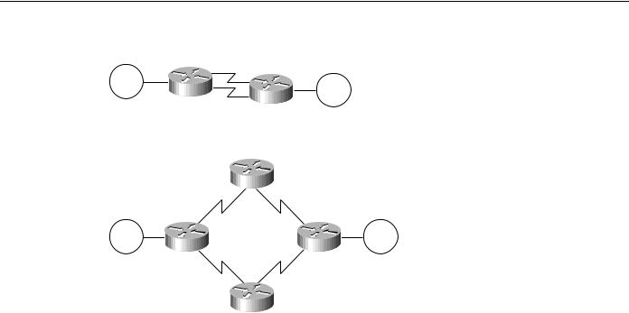
Setting up parallel links between either two routers (see Figure 4-21) or several routers (see Figure 4-22Figure 4-21) can pose challenges in an SRB environment. First, consider environments running NetBIOS and SNA over SRB environments. When an SNA or NetBIOS frame is delivered out of sequence, the end station might declare a protocol violation and terminate the session. Session loss is probably the worst possible outcome for a user or a network administrator.
Designing SRB Internetworks 4-21
SRB Technology Overview and Implementation Issues
Figure 4-21 Parallel paths between two WAN routers.
Token |
Token |
Ring |
|
|
Ring |
Figure 4-22 Parallel WAN connections among several routers.
Token |
Token |
Ring |
Ring |
Delivering frames in sequence is the key objective of any SRB delivery mechanism. When you create parallel WAN links, you expect parallel delivery. In an SRB universe, this might not be achievable because timing differences on WAN links alone can cause packet resequencing. If the router uses parallel links and starts one frame header ahead of a second frame header, the frames might not arrive with the same sequencing. The second frame might arrive before the first frame because of WAN link delays. This is particularly true of packet-switched WANs.
When selecting or applying an encapsulation strategy with parallel WAN links, other factors influence the encapsulation that is used. These factors include the WAN switching technology and the IP routing protocols. A discussion of these factors follows. Some choices are predetermined. For example, direct HDLC encapsulation voids all parallel connections across a single virtual ring. In a multiprotocol environment, you can place SRB traffic on a single parallel link, whereas other protocols are load balanced on parallel links. As an alternative, you can configure the second link exclusively for multiprotocol (non-SRB) traffic.
WAN technologies can use two primary switching types: process switching and fast switching. Process switching provides full route evaluation and per-packet load balancing across parallel WAN links. Fast switching associates an IP host destination to a single interface to avoid out of order frames. The fact that the destination of a remote peer is a single IP destination can impact SRB decisions.
Process-switching and fast-switching techniques provide different features and performance characteristics. Each technique must be applied in situations that can optimize its respective capabilities. These switching strategies are addressed in detail in the following sections, “Process Switching” and “Fast Switching.” Later in this chapter, “IP Routing Protocols with Parallel Links” addresses routing and switching in the context of SRB framing options.
Process Switching
Process switching is the most expensive switching operation that the CPU can perform. Process switching involves transmitting entire frames to the router CPU. Frames are then repackaged for delivery to or from a WAN interface, and the router makes a route selection for each packet. TCP/IP framing must be process switched because switching must occur when the rings are encapsulating or unencapsulating data, which occurs at processor level. FST framing can be process switched or fast switched.
4-22 Cisco CCIE Fundamentals: Network Design

WAN Parallelism
Process switching begins when a frame arrives on a Token Ring interface and causes an interrupt to be transmitted to the CPU. The CPU then determines that the frame must be process switched and schedules the switch in noninterrupt mode. The frame is then transferred to the CPU and placed on an input queue, whose depth is viewable with the show interfaces EXEC command. Once the entire frame is transferred across the system bus, the frame is reworked for appropriate TCP headers and header compression.
Next, the IP route for the destination is examined. If multiple paths exist, the frame pointer is updated to use the next path for the next frame that arrives. After a route is selected, the frame is transmitted across the system bus to the output interface queue of the specific interface card from which the frame will exit. The queue entry is placed on the specific exit interface and the SCI card dequeues and transmits the frame down the WAN link.
Fast Switching
Fast switching maximizes the volume of traffic that the router can handle by streamlining the router’s queuing mechanisms. Fast switching deals with incoming frames in processor interrupt mode and minimizes the number of decisions that must be applied.
Fast switching precaches routes. Once an IP destination is process switched, its route is cached and associated with a specific interface. When an IP destination is precached, it is tied to a specific path. For either FST or TCP/IP encapsulations, a single IP destination carries all of the SRB traffic to an FEP destination. If fast switching is used with multiple IP paths, a single path exists for each ring destination. You must use process switching to load-balance traffic across multiple paths.
Two of the SRB framing techniques are capable of being fast switched: direct HDLC encapsulation and FST encapsulation. Direct HDLC encapsulation is by definition fast switched; it cannot be process switched. FST can be fast switched or process switched.
Two IBM SRB WAN options do not allow fast switching of a frame: TCP header compression and priority or custom queuing. If either of these features is invoked, the frame cannot be fast switched. The reason for these caveats is that certain frame components are modified when using fast switching in AGS+, MGS, CGS, or Cisco 7000 interface memory and not in the CPU memory. If the frame needs to be extensively modified, it must be done in CPU system buffers and not in buffers associated with individual interface cards.
In addition, fast switching uses only interface buffers that are not generally reported using monitoring EXEC commands, such as show interfaces. The buffers reported in the show interfaces EXEC command are CPU buffers for input and output that are only used during process switching. Fast switching uses preconfigured interface buffers. You can view the allocation of buffers using the show controllers EXEC command.
For direct HDLC encapsulation, SRB frames are directly linked to an output serial port (such as interface serial 0). When an SRB frame enters the 2R or CTR card, an interrupt is transmitted to the CPU. The CPU verifies that the frame is an SRB frame and that the buffer on either the 2R card or the ciscoBus controller is modified to create an HDLC header. The new frame is transmitted two bytes at a time through the CPU from either the 2R card or the ciscoBus controller across the system bus to the SCI card or SIP card.
A similar process occurs for FST encapsulation; however, SRB frames are directly linked to a destination IP address. When an SRB frame enters the 2R or CTR card, an interrupt is transmitted to the CPU. The CPU verifies that the frame is an SRB frame and the buffer on either the 2R card or the ciscoBus controller is modified to create an IP datagram with appropriate WAN framing for the destination. The new frame is transmitted two bytes at a time through the CPU from either the 2R card or the ciscoBus controller across the system bus to the SCI card or SIP card.
Designing SRB Internetworks 4-23
SRB Technology Overview and Implementation Issues
Use the EXEC command show ip route cache to determine whether an IP destination is being fast switched. This command lists IP destinations as well as the relevant MAC frame and destination interface that the specific IP address uses. If the entry is fast switched, the destination IP address is present. If the destination IP address is not present, the router is using process switching to reach the destination. By default, HDLC WAN links are fast switched for IP. If the router is configured for direct HDLC encapsulation, the only status indication is the output for the show source-bridge EXEC command. The bridge indicates it is using a direct serial interface and not an IP address.
IP Routing Protocols with Parallel Links
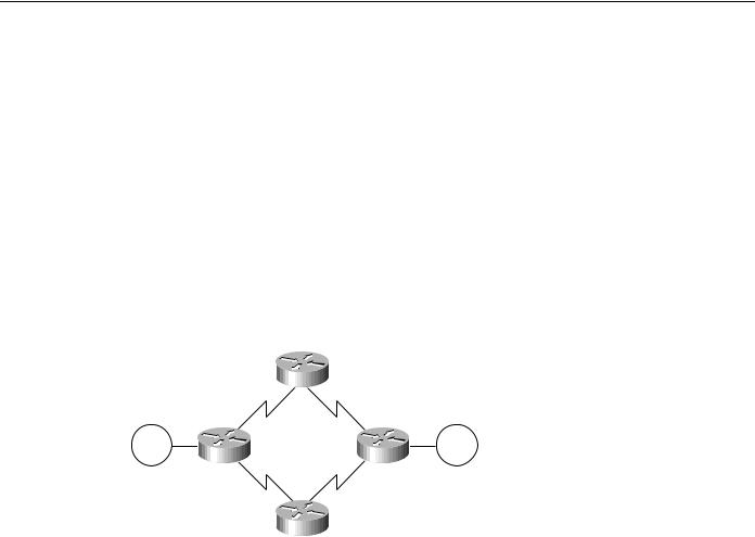
IP routing protocols play a part in the parallel SRB WAN decisions because they can create wider parallelism than two routers with parallel links. Given the parallel links shown in Figure 4-23, load balancing makes three critical assumptions: equal-cost paths, routing protocol support for equal-cost load balancing, and process switching for a single IP destination.
Figure 4-23 Parallel WAN paths.
Token |
Token |
Ring |
Ring |
Process switching is discussed extensively in the section “Process Switching” earlier in this chapter. Issues relating to equal-cost path IP routing and unequal-cost path routing are discussed in the sections that follow, “IP Routing over Equal-Cost Paths” and “IP Routing over Unequal-Cost Paths Using Variance.”
IP Routing over Equal-Cost Paths
An equal-cost path is metrically equivalent to another parallel path between two points. In RIP, equivalence is parallel WAN paths of equal hops. In Interior Gateway Routing Protocol (IGRP) and Open Shortest Path First (OSPF), metric equivalence translates into WAN paths of equal bandwidth, where the bandwidth is declared by the network administrator. IGRP also adds the concept of delay to determine metrically equivalent links. To create parallel links for equal-cost paths and to actively use these paths, the router must use process switching because all frames sent from one ring to another have the same IP destination.
The following list outlines the capability of supported IP routing technologies to create equal-cost paths:
•Static routes—For Cisco software releases prior to Software Release 9.1, static routes cannot be created in parallel; only a single path can be selected. As of Software Release 9.1, static routes can be created in parallel.
•IGRP and Enhanced Interior Gateway Routing Protocol (Enhanced IGRP)—Can use up to four equal-cost paths in parallel. Ensure that the bandwidth command is correctly configured on all links.
4-24 Cisco CCIE Fundamentals: Network Design
WAN Parallelism
•OSPF—If paths are of equal declared metrics, OSPF can use up to four equal-cost paths in parallel.
•RIP—RIP can use four equal-cost paths in parallel. Remember that this will not take into account anything but hops, so even unequal bandwidth links will be evaluated as having equivalent cost.
IGRP, Enhanced IGRP, and OSPF can route traffic across equal-cost paths and split SRB traffic across equal-cost links if the router is process switching. RIP will route across equal-cost paths and it will assume that all WAN links are the same speed regardless of reality. Static routes allow parallel paths and are a tool for the advanced network designer.
A router’s capability to use parallel paths is determined in part by the encapsulation method. If TCP/IP encapsulation is used, parallel paths are used. If FST encapsulation is used under normal operational conditions, all traffic must use only one of the parallel links. This is because all the RSRB traffic sent to another FST peer goes to a single IP destination address. When using fast switching, the router might alternate some traffic across parallel links based on destination address. However, because all traffic to a peer router uses only one destination IP address, all RSRB traffic flows across one link.
IP Routing over Unequal-Cost Paths Using Variance
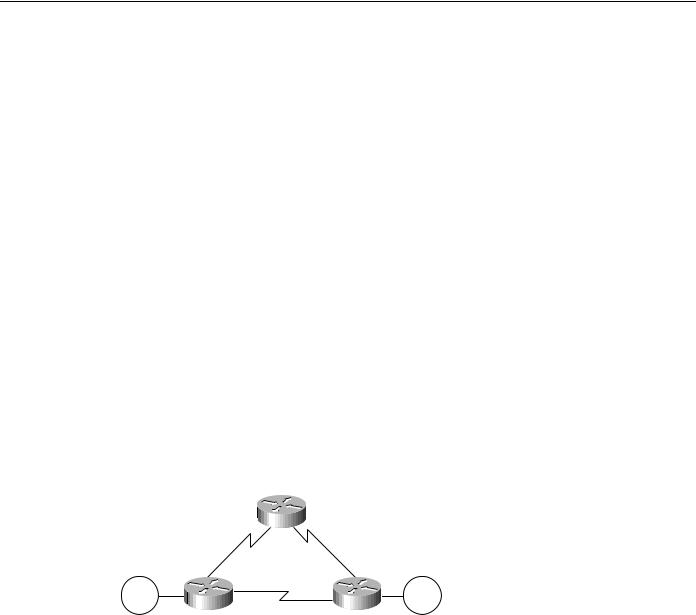
The only routing protocols that can handle intentional unequal-cost path balancing are IGRP and Enhanced IGRP. Using a feature called variance, the router can load balance over unequal-cost paths. Figure 4-24 illustrates one such configuration from A to B. In this figure, load balancing the link from C to B is assumed to be faster than the link from A to B.
Figure 4-24 Unequal-cost load balancing with IGRP.
C
Token |
Token |
Ring |
Ring |
A |
B |
Variance has two rules that apply in this or any unequal-cost load balancing situation:
•Rule 1—Parallelism must exist in the topology.
•Rule 2—Packets must make forward progress on any parallel link toward an intended destination. In other words, a router will not forward traffic to another router that has the same (or greater) relative distance metric to a destination. This rule prevents loops. The rule of forward progress is straightforward. If the next-hop router is closer to the destination (than some other router) a path through it will be used as a valid alternative path.
If these rules are met and the network administrator adds variance to the IGRP configuration, the router will load balance over parallel paths for a single IP destination when it is process switching. Figure 4-25 illustrates a case in which variance might be used.
Designing SRB Internetworks 4-25
SRB Technology Overview and Implementation Issues
Figure 4-25 Environmental illustrating variance applications.
|
London |
1.5 Mbps |
64 kbps |
New York |
Prague |
Token |
Token |
Ring |
Ring |
56 kbps |
2 Mbps |
|
Paris
Consider a set of routers connected via WAN links in a circle, where each WAN link is the same speed, as illustrated in Figure 4-26. Assume that a data center is at location A and that all the link speeds are the same. Consider parallelism from B to A. A parallel link exists from A to B and A to C to D to E to B; however, routing protocols are not intuitive. This topology satisfies the first rule because parallelism clearly exists; however, this topology fails the forward progress rule.
The way to evaluate the forward progress rule is to examine the obvious short path separately from the long variant path, subtracting the first hop. Is C to D to E to B a better path than A to B? The answer is no; variance will have no effect in this topology for the problem as described.
Figure 4-26 Unequal-cost path and variance implementation example.
D
C E
Token |
Token |
Ring |
Ring |
A |
B |
Now evaluate the problem from the perspective of A to E. Using the forward progress rule, compare A to B to E with C to D to E. In this topology, these paths are equal and they fail the forward progress rule. If these paths are to pass data in parallel, router A must have two paths: one to C and one to B. If C had variance configured, it would have two paths: one to A and one to D. This leaves the possibility of C routing to A and A routing to C in a loop. Thus, the variance rule is that the metric of the next-hop router must be less than the metric through the shortest path. In a five-router topology with equal-cost WAN links, parallelism cannot be achieved.
4-26 Cisco CCIE Fundamentals: Network Design

WAN Parallelism
By default, variance is not configured. If it is, it must be configured as an integer multiple of the allowable metric variance. Consider the following use of the variance router configuration command:
router igrp 1343 variance 2
Using this particular instance of the variance command results in a load-balanced topology with a 2:1 ratio of bandwidth. For all practical topologies, this should be an upper maximum because you should not load balance an overly high variance of WAN links such as E1 and 64 Kbps.
Use variance carefully. Because IP fast switching links an IP destination to an interface or next hop, a single IP destination can be stuck on a 64-Kbps link while most other IP destinations are wired to a fast link such as an E1. This situation will cause users to call their network administrators to determine why transmission is slow one day when it was fast the day before. If SRB is fast switched, all users of a destination ring can be linked to the slower path using variance.
Variance has another major benefit: If a link fails for any reason, the router immediately switches all traffic to the parallel link without any convergence overhead. The router can do this because the parallel link is a known valid path and the router does not need to wait for the routing protocols to converge.
Local Acknowledgment Recommendations
If you configure your remote source-route bridge to use IP encapsulation over a TCP connection, you also can enable LLC2 Local Acknowledgment. The following explains how this feature can be useful.
LLC2, or Logical Link Control-Type 2, an ISO standard data link level protocol used in Token Ring networks, was designed to ensure reliable transmission of data across LAN media with minimal or predictable time delays. With the advent of remote source route bridging (RSRB) and wide area network (WAN) backbones, LANs are now separated by wide, geographic distances spanning countries and continents. As a result, these LANs have time delays that are longer than LLC2 allows for bidirectional communication between hosts. The Local Acknowledgment capability in router/bridges supporting remote source-route bridging addresses the problem of unpredictable time delays, multiple retransmissions, and many user sessions.
In a typical LLC2 session, when host A sends a frame to host B, the sending host A expects host B to respond positively or negatively in a certain amount of predefined time commonly called the T1 time. If host A does not receive an acknowledgment of the frame it sent to host B within the T1 time, it will retry a few number of times (normally 8 to 10). If there is still no response from host B, host A will drop the session.
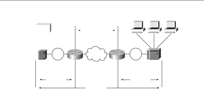
Figure 4-27 shows how Local Acknowledgment operates in an SRB environment. With Local Acknowledgment for LLC2 enabled in both routers, Router A acknowledges frames received from the 37x5. The 37x5 still thinks that the acknowledgments it receives are from the 3x74. The 3x74 thinks that the acknowledgments it receives are from the 37x5. Router B looks like the 3x74 to 37x5. Because the frames no longer have to travel the WAN backbone networks to be acknowledged, but instead are locally acknowledged by routers, the end machines do not time out, resulting in no loss of sessions.
Designing SRB Internetworks 4-27
SRB Technology Overview and Implementation Issues
Figure 4-27 How Local Acknowledgment operates in an SRB environment.
|
|
|
|
|
|
TCP Session |
|
|
|
|
|
|
|
|
|
|
|
|
|
|
|
|
|
Host |
|
|
|
|
|
|
|
|
|
|
|
|
|
|
|
|
|
|
|
||||
|
|
|
|
|
|
|
|
|
|
|
|
|
|
|
|
|
|||||||
|
|
|
|
|
|
|
|
|
|
|
|
|
|
|
|
|
|
|
|
|
|
|
|
|
|
|
|
|
|
|
|
|
|
|
|
|
|
|
|
|
|
|
|
|
|
|
|
Token |
|
WAN |
Token |
|
Ring |
Router A |
Ring |
||
Router B |
||||
37x5 |
|
|
3x74 |
|
LLC2 session |
|
|
LLC2 session |
SNA Session
The following recommendations apply to the implementation of local acknowledgment. Use local acknowledgment under the following conditions:
•When the WAN implementation must accommodate long network delays
•When the internetwork includes slow links, heavily used links, or poor quality links
•When the internetwork requires that sessions remain active during router convergence
•When WAN traffic must be minimized
•When the amount of LLC traffic on backbone needs to be reduced (when more than 50 percent of packets are LLC packets)
•When WAN costs must be reduced
•When network integrity must be improved, assuming TCP/IP encapsulation is used
•When unreliable WAN links exist that are causing frequent session loss
•When end station timer or retry modifications are difficult or costly
•When bandwidth constraints require the elimination of acknowledgment traffic
Parallel Link Recommendations
The following recommendations apply to parallel WAN link configuration:
•Do not combine multiple CTR cards with multiple WAN links; create a separate router primarily with WAN links. For example, do not create an 8-T1/E1 process-switched WAN solution on top of a 75-kilopackets-per-second (Kpps) Token Ring engine. You will run out of CPU bandwidth.
•Use FST encapsulation whenever possible.
•Use TCP/IP encapsulation when local acknowledgment or prioritization is required.
•Maximize fast switching.
When link speeds are primarily 64 Kbps and slower and local acknowledgment or prioritization is a requirement, use TCP/IP encapsulation with IGRP variance in meshed topologies when the topology can take advantage of these features.
When link speeds are primarily greater than 64 Kbps and local acknowledgment is a requirement, follow this recommendation:
4-28 Cisco CCIE Fundamentals: Network Design