

Cisco. Fundamentals Network Design - Cisco Press
.pdfEvaluating Local-Access Services
Network applications and connection services provided over segmented internetworks require a rational way to resolve names to addresses. Various facilities accommodate this requirement. Any router you select must support the name services implemented for different end-system environments. Examples of supported name services include NetBIOS, IP’s Domain Name System (DNS) and IEN-116, and AppleTalk Name Binding Protocol (NBP).
A router can also act as a proxy for a name server. The router’s support of NetBIOS name caching is one example of this kind of capability. NetBIOS name caching allows the router to maintain a cache of NetBIOS names, which avoids the overhead of transmitting all of the broadcasts between client and server NetBIOS PCs (IBM PCs or PS/2s) in an SRB environment. When NetBIOS name caching is enabled, the router does the following:
•Notices when any host sends a series of duplicate query frames and limits retransmission to one frame per period. The time period is a configuration parameter.
•Keeps a cache of mappings between NetBIOS server and client names and their MAC addresses. As a result, broadcast requests sent by clients to find servers (and by servers in response to their clients) can be sent directly to their destinations, rather than being broadcast across the entire bridged network.
When NetBIOS name caching is enabled and default parameters are set on the router, the NetBIOS name server, and the NetBIOS name client, approximately 20 broadcast packets per login are kept on the local ring where they are generated.
In most cases, the NetBIOS name cache is best used when large amounts of NetBIOS broadcast traffic might create bottlenecks on a WAN that connects local internetworks to distant locations.
The router can also save bandwidth (or handle nonconforming name resolution protocols) by using a variety of other proxy facilities. By using routers to act on behalf of other devices to perform various functions, you can more easily scale networks. Instead of being forced to add bandwidth when a new workgroup is added to a location, you can use a router to manage address resolution and control message services. Examples of this kind of capability include the proxy explorer feature of SRB and the proxy polling feature of STUN implementations.
Sometimes portions of networks cannot participate in routing activity or do not implement software that conforms to generally implemented address-resolution protocols. Proxy implementations on routers allow network designers to support these networks or hosts without reconfiguring an internetwork. Examples of these kinds of capabilities include proxy ARP address resolution for IP internetworks and NBP proxy in AppleTalk internetworks.
Local caches store previously learned information about the network so that new information requests do not need to be issued each time the same piece of information is desired. A router’s ARP cache stores physical address and network address mappings so that it does not need to broadcast ARP requests more than once within a given time period for the same address. Address caches are maintained for many other protocols as well, including DECnet, Novell IPX, and SRB, where RIF information is cached.
Media Access Security
If all corporate information is readily available to all employees, security violations and inappropriate file access can occur. To prevent this, routers must do the following:
•Keep local traffic from inappropriately reaching the backbone
•Keep backbone traffic from exiting the backbone into an inappropriate department or workgroup network
Internetworking Design Basics 2-25

Identifying and Selecting Internetworking Capabilities
These two functions require packet filtering. Packet filtering capabilities should be tailored to support a variety of corporate policies. Packet filtering methods can reduce traffic levels on a network, thereby allowing a company to continue using its current technology rather than investing in more network hardware. In addition, packet filters can improve security by keeping unauthorized users from accessing information and can minimize network problems caused by excessive congestion.
Routers support many filtering schemes designed to provide control over network traffic that reaches the backbone. Perhaps the most powerful of these filtering mechanisms is the access list. Each of the following possible local-access services can be provided through access lists:
•You have an Ethernet-to-Internet routing network and you want any host on the Ethernet to be able to form TCP connections to any host on the Internet. However, you do not want Internet hosts to be able to form TCP connections into the Ethernet except to the SMTP port of a dedicated mail host.
•You want to advertise only one network through a RIP routing process.
•You want to prevent packets that originated on any Sun workstation from being bridged on a particular Ethernet segment.
•You want to keep a particular protocol based on Novell IPX from establishing a connection between a source network or source port combination and a destination network or destination port combination.
Access lists logically prevent certain packets from traversing a particular router interface, thereby providing a general tool for implementing network security. In addition to this method, several specific security systems already exist to help increase network security. For example, the U.S. government has specified the use of an optional field within the IP packet header to implement a hierarchical packet security system called the Internet Protocol Security Option (IPSO).
IPSO support on routers addresses both the basic and extended security options described in a draft of the IPSO circulated by the Defense Communications Agency. This draft document is an early version of Request for Comments (RFC) 1108. IPSO defines security levels (for example, TOP SECRET, SECRET, and others) on a per-interface basis and accepts or rejects messages based on whether they include adequate authorization.
Some security systems are designed to keep remote users from accessing the network unless they have adequate authorization. For example, the Terminal Access Controller Access Control System (TACACS) is a means of protecting modem access into a network. The Defense Data Network (DDN) developed TACACS to control access to its TAC terminal servers.
The router’s TACACS support is patterned after the DDN application. When a user attempts to start an EXEC command interpreter on a password-protected line, TACACS prompts for a password. If the user fails to enter the correct password, access is denied. Router administrators can control various TACACS parameters, such as the number of retries allowed, the timeout interval, and the enabling of TACACS accounting.
The Challenge Handshake Authentication Protocol (CHAP) is another way to keep unauthorized remote users from accessing a network. It is also commonly used to control router-to-router communications. When CHAP is enabled, a remote device (for example, a PC, workstation, router, or communication server) attempting to connect to a local router is “challenged” to provide an appropriate response. If the correct response is not provided, network access is denied.
CHAP is becoming popular because it does not require a secret password to be sent over the network. CHAP is supported on all router serial lines using Point-to-Point Protocol (PPP) encapsulation.
2-26 Cisco CCIE Fundamentals: Network Design

Choosing Internetworking Reliability Options
Router Discovery
Hosts must be able to locate routers when they need access to devices external to the local network. When more than one router is attached to a host’s local segment, the host must be able to locate the router that represents the optimal path to the destination. This process of finding routers is called router discovery.
The following are router discovery protocols:
•End System-to-Intermediate System (ES-IS)—This protocol is defined by the ISO OSI protocol suite. It is dedicated to the exchange of information between intermediate systems (routers) and end systems (hosts). ESs send “ES hello” messages to all ISs on the local subnetwork. In turn, “IS hello” messages are sent from all ISs to all ESs on the local subnetwork. Both types of messages convey the subnetwork and network-layer addresses of the systems that generate them. Using this protocol, end systems and intermediate systems can locate one another.
•ICMP Router Discovery Protocol (IRDP)—Although the issue is currently under study, there is currently no single standardized manner for end stations to locate routers in the IP world. In many cases, stations are simply configured manually with the address of a local router. However, RFC 1256 outlines a router discovery protocol using the Internet Control Message Protocol (ICMP). This protocol is commonly referred to as IRDP.
•Proxy Address Resolution Protocol (ARP)—ARP uses broadcast messages to determine the MAC-layer address that corresponds to a particular internetwork address. ARP is sufficiently generic to allow use of IP with virtually any type of underlying media-access mechanism. A router that has proxy ARP enabled responds to ARP requests for those hosts for which it has a route, which allows hosts to assume that all other hosts are actually on their network.
•RIP—RIP is a routing protocol that is commonly available on IP hosts. Many hosts use RIP to find the address of the routers on a LAN or, when there are multiple routers, to pick the best router to use for a given internetwork address.
Cisco routers support all the router discovery protocols listed. You can choose the router discovery mechanism that works best in your particular environment.
Choosing Internetworking Reliability Options
One of the first concerns of most network designers is to determine the required level of application availability. In general, this key consideration is balanced against implementation cost. For most organizations, the cost of making a network completely fault tolerant is prohibitive. Determining the appropriate level of fault tolerance to be included in a network and where redundancy should be used is not trivial.
The nonredundant internetwork design in Figure 2-18 illustrates the considerations involved with increasing levels of internetwork fault tolerance.
Internetworking Design Basics 2-27
Identifying and Selecting Internetworking Capabilities
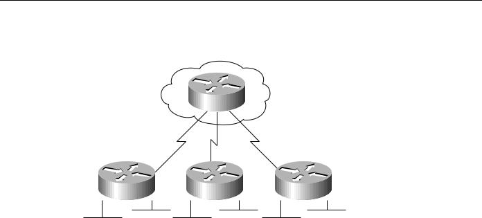
Figure 2-18 Typical nonredundant internetwork design.
Corporate office
Router
Router |
Router |
Router |
Remote office 1 |
Remote office 2 |
Remote office 3 |
The internetwork shown in Figure 2-18 has two levels of hierarchy: a corporate office and remote offices. Assume the corporate office has eight Ethernet segments, to which approximately 400 users (an average of 50 per segment) are connected. Each Ethernet segment is connected to a router. In the remote offices, two Ethernet segments are connected to the corporate office through a router. The router in each remote office is connected to the router in the corporate office through a T1 link.
The following sections address various approaches to creating redundant internetworks, provide some context for each approach, and contrast their relative merits and drawbacks. The following four sections are provided:
•
•
•
•
Redundant Links Versus Meshed Topologies
Redundant Power Systems
Fault-Tolerant Media Implementations
Backup Hardware
Redundant Links Versus Meshed Topologies
Typically, WAN links are the least reliable components in an internetwork, usually because of problems in the local loop. In addition to being relatively unreliable, these links are often an order of magnitude slower than the LANs they connect. However, because they are capable of connecting geographically diverse sites, WAN links often make up the backbone network, and are therefore critical to corporate operations. The combination of potentially suspect reliability, lack of speed, and high importance makes the WAN link a good candidate for redundancy.
As a first step in making the example internetwork more fault tolerant, you might add a WAN link between each remote office and the corporate office. This results in the topology shown in Figure 2-19. The new topology has several advantages. First, it provides a backup link that can be used if a primary link connecting any remote office and the corporate office fails. Second, if the routers support load balancing, link bandwidth has now been increased, lowering response times for users and increasing application availability.
2-28 Cisco CCIE Fundamentals: Network Design
Choosing Internetworking Reliability Options
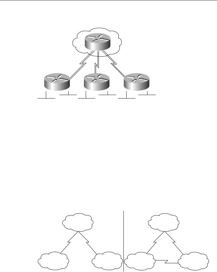
Figure 2-19 Internetwork with dual links to remote offices.
Corporate office
Router
Router |
Router |
Router |
Remote office 1 |
Remote office 2 |
Remote office 3 |
Load balancing in transparent bridging and IGRP environments is another tool for increasing fault tolerance. Routers also support load balancing on either a per-packet or a per-destination basis in all IP environments. Per-packet load balancing is recommended if the WAN links are relatively slow (for example, less than 56 Kbps). If WAN links are faster than 56 Kbps, enabling fast switching on the routers is recommended. When fast switching is enabled, load balancing occurs on a perdestination basis.
Routers can automatically compensate for failed WAN links through routing algorithms of protocols, such as IGRP, OSPF, and IS-IS. If one link fails, the routing software recalculates the routing algorithm and begins sending all traffic through another link. This allows applications to proceed in the face of WAN link failure, improving application availability.
The primary disadvantage of duplicating WAN links to each remote office is cost. In the example outlined in Figure 2-19, three new WAN links are required. In large star networks with more remote offices, 10 or 20 new WAN links might be needed, as well as new equipment (including new WAN router interfaces). A lower cost alternative that is becoming increasingly popular links the remote offices using a meshed topology, as shown in Figure 2-20.
Figure 2-20 Evolution from a star to a meshed topology.
Before |
|
After |
|
Corporate office |
|
Corporate office |
|
A |
B |
A |
B |
Remote office 1 |
Remote office 2 |
Remote office 1 |
Remote office 2 |
C
Internetworking Design Basics 2-29

Identifying and Selecting Internetworking Capabilities
In the “before” portion of Figure 2-20, any failure associated with either Link A or B blocks access to a remote site. The failure might involve the link connection equipment, such as a data service unit (DSU) or a channel service unit (CSU), the router (either the entire router or a single router port), or the link itself. Adding Link C as shown in the “after” portion of the figure, offsets the effect of a failure in any single link. If Link A or B fails, the affected remote site can still access the corporate office through Link C and the other site’s link to the corporate office. Note also that if Link C fails, the two remote sites can communicate through their connections to the corporate office.
A meshed topology has three distinct advantages over a redundant star topology:
•A meshed topology is usually slightly less expensive (at least by the cost of one WAN link).
•A meshed topology provides more direct (and potentially faster) communication between remote sites, which translates to greater application availability. This can be useful if direct traffic volumes between remote sites are relatively high.
•A meshed topology promotes distributed operation, preventing bottlenecks on the corporate router and further increasing application availability.
A redundant star is a reasonable solution under the following conditions:
•Relatively little traffic must travel between remote offices.
•Traffic moving between corporate and remote offices is delay sensitive and mission critical. The delay and potential reliability problems associated with making an extra hop when a link between a remote office and the corporate office fails might not be tolerable.
Redundant Power Systems
Power faults are common in large-scale networks. Because they can strike across a very local or a very wide scale, power faults are difficult to preempt. Simple power problems include dislodged power cords, tripped circuit breakers, and local power supply failures. More extensive power problems include large-scale outages caused by natural phenomena (such as lightning strikes) or brown-outs. Each organization must assess its needs and the probability of each type of power outage before determining which preventative actions to take.
You can take many precautions to try to ensure that problems, such as dislodged power cords, do not occur frequently. These fall outside the scope of this publication and will not be discussed here. This chapter focuses on issues addressable by internetworking devices.
From the standpoint of internetworking devices, dual power systems can prevent otherwise debilitating failures. Imagine a situation where the so-called backbone-in-a-box configuration is being used. This configuration calls for the connection of many networks to a router being used as a connectivity hub. Benefits include a high-speed backbone (essentially the router’s backplane) and cost efficiency (less media). Unfortunately, if the router’s power system becomes faulty, each network connected to that router loses its capability to communicate with all other networks connected to that router.
Some backbone-in-a-box routers can address this requirement by providing redundant power systems. In addition, many sites connect one power system to the local power grid and the other to an uninterruptable power supply. If router power fails, the router can continue to provide connectivity to each connected network.
General power outages are usually more common than failures in a router’s power system. Consider the effect of a site-wide power failure on redundant star and meshed topologies. If the power fails in the corporate office, the organization might be seriously inconvenienced. Key network applications are likely to be placed at a centralized, corporate location. The organization could easily lose revenue for every minute its network is down. The meshed network configuration is superior in this case because links between the remote offices would still be able to communicate with each other.
2-30 Cisco CCIE Fundamentals: Network Design
Choosing Internetworking Reliability Options
If power fails at a remote site, all connections to that remote site will be terminated unless otherwise protected. Neither the redundant star nor the meshed topology is superior. In both cases, all other remote offices will still be able to communicate with the corporate office. Generally, power failures in a remote office are more serious when network services are widely distributed.
To protect against local and site-wide power outages, some companies have negotiated an arrangement with local power companies to use multiple power grids within their organization. Failure within one power grid will not affect the network if all critical components have access to multiple power grids. Unfortunately, this arrangement is very expensive and should only be considered by companies with substantial resources, extremely mission-critical operations, and a relatively high likelihood of power failures.
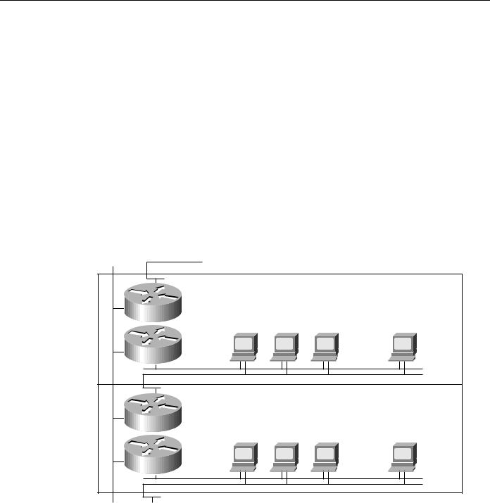
The effect of highly localized power failures can be minimized with prudent network planning. Wherever possible, redundant components should use power supplied by different circuits. Further, these redundant components should not be physically colocated. For example, if redundant routers are employed for all stations on a given floor, these routers can be physically stationed in wiring closets on different floors. This prevents local wiring closet power problems from affecting the capability of all stations on a given floor to communicate. Figure 2-21 shows such a configuration.
Figure 2-21 Redundant components on different floors.
To other routers |
To end stations on floor X+2 |
|
Floor X+1 |
|
Router |
|
End stations |
|
Router |
|
Shared media LANs |
|
Floor X |
|
Router |
|
End stations |
|
Router |
|
Shared media LANs |
To other routers Router on floor X-1
For some organizations, the need for fault tolerance is so great that potential power failures are protected against with a duplicate corporate data center. Organizations with these requirements often locate a redundant data center in another city, or in a part of the same city that is some distance from the primary data center. All backend services are duplicated, and transactions coming in from remote offices are sent to both data centers. This configuration requires duplicate WAN links from all remote offices, duplicate network hardware, duplicate servers and server resources, and leasing another building. Because this approach is so costly, it is typically the last step taken by companies desiring the ultimate in fault tolerance.
Partial duplication of the data center is also a possibility. Several key servers and links to those servers can be duplicated. This is a common compromise to the problem presented by power failures.
Internetworking Design Basics 2-31

Identifying and Selecting Internetworking Capabilities
Fault-Tolerant Media Implementations
Media failure is another possible network fault. Included in this category are all problems associated with the media and its link to each individual end station. Under this definition, media components include network interface controller failures, lobe or attachment unit interface (AUI) cable failures, transceiver failures, hub failures, and all failures associated with media components (for example, the cable itself, terminators, and other parts). Many media failures are caused by operator negligence and cannot easily be eliminated.
One way to reduce the havoc caused by failed media is to divide existing media into smaller segments and support each segment with different hardware. This minimizes the effect of a failure on a particular segment. For example, if you have 100 stations attached to a single switch, move some of them to other switches. This reduces the effect of a hub failure and of certain subnetwork failures. If you place an internetworking device (such as a router) between segments, you protect against additional problems and cut subnetwork traffic.
As shown in Figure 2-21, redundancy can be employed to help minimize media failures. Each station in this figure is attached to two different media segments. NICs, hub ports, and interface cables are all redundant. This approach doubles the cost of network connectivity for each end station as well as the port usage on all internetworking devices, and is therefore only recommended in situations where complete redundancy is required. It also assumes that end station software, including both the network and the application subsystems, can handle and effectively use the redundant components. The application software or the networking software or both must be able to detect network failures and initiate use of the other network.
Certain media access protocols have some fault-tolerant features built in. Token Ring multistation access units (MAUs) can detect certain media connection failures and bypass the failure internally. FDDI dual rings can wrap traffic onto the backup ring to avoid portions of the network with problems.
From a router’s standpoint, many media failures can be bypassed so long as alternative paths are available. Using various hardware detection techniques, routers can sense certain media-level problems. If routing updates or routing keepalive messages have not been received from devices that would normally be reached through a particular router port, the router will soon declare that route down and will look for alternative routes. Meshed networks provide these alternative paths, allowing the router to compensate for media failures.
Backup Hardware
Like all complex devices, routers, switches, and other internetworking devices develop hardware problems. When serious failures occur, the use of dual devices can effectively reduce the adverse effects of a hardware failure. After a failure, discovery protocols help end stations choose new paths with which to communicate across the network. If each network connected to the failed device has an alternative path out of the local area, complete connectivity will still be possible.
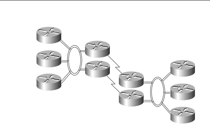
For example, when backup routers are used, routing metrics can be set to ensure that the backup routers will not be used unless the primary routers are not functioning. Switchover is automatic and rapid. For example, consider the situation shown in Figure 2-22. In this network, dual routers are used at all sites with dual WAN links. If Router R1 fails, the routers on FDDI 1 will detect the failure by the absence of messages from Router R1. Using any of several dynamic routing protocols, Router A, Router B, and Router C will designate Router R3 as the new next hop on the way to remote resources accessible via Router R4.
2-32 Cisco CCIE Fundamentals: Network Design
|
|
Identifying and Selecting Internetworking Devices |
|
Figure 2-22 |
Redundant FDDI router configuration. |
|
|
|
Local site |
|
|
Router A |
FDDI 1 |
|
|
|
|
|
|
|
Router R1 |
|
|
Router B |
|
Remote site |
|
|
|
|
|
|
Router R3 |
FDDI 2 |
Router X |
|
|
|
|
Router R2
Router C
Router Y
Router R4
Router Z
Many networks are designed with multiple routers connecting particular LANs in order to provide redundancy. In the past, the effectiveness of this design was limited by the speed at which the hosts on those LANs detected a topology update and changed routers. In particular, IP hosts tend to be configured with a default gateway or configured to use Proxy ARP in order to find a router on their LAN. Convincing an IP host to change its router usually required manual intervention to clear the ARP cache or to change the default gateway.
The Hot Standby Router Protocol (HSRP) is a solution that allows network topology changes to be transparent to the host. HSRP typically allows hosts to reroute in approximately 10 seconds. HSRP is supported on Ethernet, Token Ring, FDDI, Fast Ethernet, and ATM.
An HSRP group can be defined on each LAN. All members of the group know the standby IP address and the standby MAC address. One member of the group is elected the leader. The lead router services all packets sent to the HSRP group address. The other routers monitor the leader and act as HSRP routers. If the lead router becomes unavailable, the HSRP router elects a new leader who inherits the HSRP MAC address and IP address.
High-end routers (Cisco 4500, 7000, and 7500 families) can support multiple MAC addresses on the same Ethernet or FDDI interface, allowing the routers to simultaneously handle both traffic that is sent to the standby MAC address and the private MAC address. The commands for enabling HSRP and configuring an HSRP group are standby ip and standby group.
Identifying and Selecting Internetworking Devices
Network designers have four basic types of internetworking devices available to them:
•
•
•
•
Hubs (concentrators)
Bridges
Switches
Routers
Internetworking Design Basics 2-33

Identifying and Selecting Internetworking Devices
For a summary of these four internetworking devices, see Table 2-1 earlier in this chapter. Data communications experts generally agree that network designers are moving away from bridges and primarily using switches and routers to build internetworks. Consequently, this section focuses on the role of switches and routers in designing internetworks.
Switches can be functionally divided into two main groups: Layer 2 switches and multilayer switches that provide Layer 2 and Layer 3 switching capabilities. Today, network designers are replacing hubs in their wiring closets with switches to increase their network performance and protect their existing wiring investments.
Routers segment network traffic based on the destination network layer address (Layer 3) rather than the workstation data link layer or MAC address. Consequently, routers are protocol dependent.
Benefits of Switches (Layer 2 Services)
An individual Layer 2 switch might offer some or all of the following benefits:
•Bandwidth—LAN switches provide excellent performance for individual users by allocating dedicated bandwidth to each switch port. Each switch port represents a different network segment. This technique is known as microsegmenting.
•VLANs—LAN switches can group individual ports into switched logical workgroups called VLANs, thereby restricting the broadcast domain to designated VLAN member ports. VLANs are also known as switched domains and autonomous switching domains. Communication between VLANs requires a router.
•Automated packet recognition and translation—This capability allows the switch to translate frame formats automatically, such as Ethernet MAC to FDDI SNAP.
Benefits of Routers (Layer 3 Services)
Because routers use Layer 3 addresses, which typically have structure, routers can use techniques (such as address summarization) to build networks that maintain performance and responsiveness as they grow in size. By imposing structure (usually hierarchical) on a network, routers can effectively use redundant paths and determine optimal routes even in a dynamically changing network.
Routers are necessary to ensure scalability as the network grows and expands. They provide the following capabilities that are vital in network designs:
•
•
•
•
•
Broadcast and multicast control
Broadcast segmentation
Security
Quality of service (QoS)
Multimedia
Backbone Routing Options
In an ideal world, the perfect enterprise-wide internetwork would feature a single, bullet-proof network protocol capable of transporting all manner of data communications seamlessly, error free, and with sufficient resilience to accommodate any unforeseen connectivity disruption. However, in the real world, there are many protocols with varying levels of resilience.
In designing a backbone for your organization, you might consider several options. These options are typically split into the following two primary categories:
2-34 Cisco CCIE Fundamentals: Network Design