

Cisco. Fundamentals Network Design - Cisco Press
.pdf
|
|
|
|
|
|
|
|
|
|
|
|
|
|
|
|
|
|
|
|
Addressing and Route Summarization |
||||||||||||
Figure 3-2 |
Route summarization example. |
|
|
|
|
|
|
|
|
|
|
|
|
|
|
|
|
|
|
|
||||||||||||
|
|
|
|
|
|
|
|
Router R1 |
|
|
|
|
|
|
|
|
|
|
|
|
|
|
|
|
|
|
|
|||||
|
|
|
|
|
|
|
|
routing table |
|
|
|
|
|
|
|
|
|
|
|
|
|
|
|
|
|
|
|
|||||
|
|
|
|
|
|
Destination |
Next hop |
|
|
|
|
|
|
|
|
|
|
|
|
|
|
|||||||||||
|
|
|
|
|
|
A1 |
Direct |
|
|
|
|
|
|
|
|
|
|
|
Router R4 |
|||||||||||||
|
|
|
|
|
|
A2 |
Direct |
|
|
|
|
|
|
|
|
|
|
routing table |
||||||||||||||
|
|
|
|
|
|
A3 |
R3 |
|
|
|
|
|
|
|
|
Destination |
Next hop |
|||||||||||||||
|
|
|
|
|
|
A4 |
R2 |
|
|
|
|
|
|
|
|
|||||||||||||||||
|
Router R2 |
|
|
|
A5 |
R3 |
|
|
|
|
|
|
|
|
B1 |
|
|
|
|
|
|
Direct |
||||||||||
|
routing table |
|
|
|
B1 |
Direct |
|
|
|
|
|
|
|
|
B2 |
|
|
|
|
|
|
Direct |
||||||||||
|
Destination |
Next hop |
|
|
|
B2 |
R4 |
|
|
|
|
|
|
|
|
B3 |
|
|
|
|
|
|
Direct |
|||||||||
|
|
|
|
B3 |
R4 |
|
|
|
|
|
|
|
|
B4 |
|
|
|
|
|
|
Direct |
|||||||||||
|
A1 |
Direct |
|
|
|
B4 |
R4 |
|
|
|
|
|
|
|
|
A |
|
|
|
|
|
|
R1 |
|
||||||||
|
A3 |
Direct |
|
|
|
|
|
|
|
|
|
|
|
|
|
|
|
|
|
|
|
|
|
|
|
|
|
|
|
|
|
|
|
A2 |
R1 |
|
|
|
|
|
|
|
|
|
|
|
|
|
|
|
|
|
|
|
|
|
|
|
|
|
|
|
|
|
|
|
A4 |
Direct |
|
|
|
|
|
|
|
|
|
|
|
|
|
|
|
|
|
|
|
|
|
|
|
|
|
|
|
|
|
|
|
A5 |
R3 |
|
|
|
|
|
|
|
|
|
|
|
|
|
|
|
|
|
|
|
|
|
|
|
|
|
|
|
|
|
|
|
B |
R1 |
|
|
|
|
|
|
|
|
|
|
|
|
|
|
|
|
|
|
|
|
|
|
|
|
|
|
|
|
|
|
|
|
|
|
|
|
|
|
Router |
|
R1 |
|
|
|
B1 |
|
|
|
Router |
|
R4 |
|
|
|
Token B4 |
||||||||
|
|
|
|
|
|
|
|
|
|
|
|
|
|
|
|
|
|
|||||||||||||||
|
|
|
|
|
|
|
|
|
|
|
|
|
FDDI |
|
|
|
|
|
|
|
|
|||||||||||
|
|
|
|
|
|
|
|
|
|
|
|
|
|
|
|
|
|
|
|
|
Ring |
|||||||||||
|
|
|
|
|
|
|
||||||||||||||||||||||||||
|
|
|
|
|
|
|
||||||||||||||||||||||||||
|
|
|
|
|
A1 |
|
|
|
A2 |
|
|
B2 |
|
|
|
|
|
B3 |
|
|
|
|||||||||||
|
|
|
|
|
|
|
|
|
Ethernet |
|
|
Ethernet |
||||||||||||||||||||
|
|
|
|
|
|
|
|
|
|
|
|
|
|
|
|
|
|
|
|
|
|
|||||||||||
|
|
|
|
|
|
|
|
|
A3 |
|
|
|
|
|
|
|
|
|
|
|
|
|
|
|
|
|
|
|
|
|
|
|
|
|
|
|
|
|
|
|
|
|
|
|
|
|
|
|
|
|
|
|
|
|
|
|
|
|
|
|
|
|
|
||
|
|
|
Router |
R2 |
|
|
|
|
|
Router |
R3 |
|
|
|
|
|
|
|
|
|
|
|
|
|
|
|
||||||
|
|
|
|
|
|
|
|
|
|
|
|
|
|
|
|
|
|
|
|
|
|
|
|
|
|
|
|
|
|
|||
|
|
|
|
A4 |
|
|
|
Token |
|
|
|
|
|
|
|
|
|
|
|
|
|
|
||||||||||
|
|
|
Ethernet |
|
|
|
|
Ring A5 |
|
|
|
|
|
|
|
|
|
|
|
|
|
|
||||||||||
|
|
|
|
|
|
|
|
|
|
|
|
|
|
|
|
|
|
|
|
|
|
|
|
|
|
|
|
|
||||
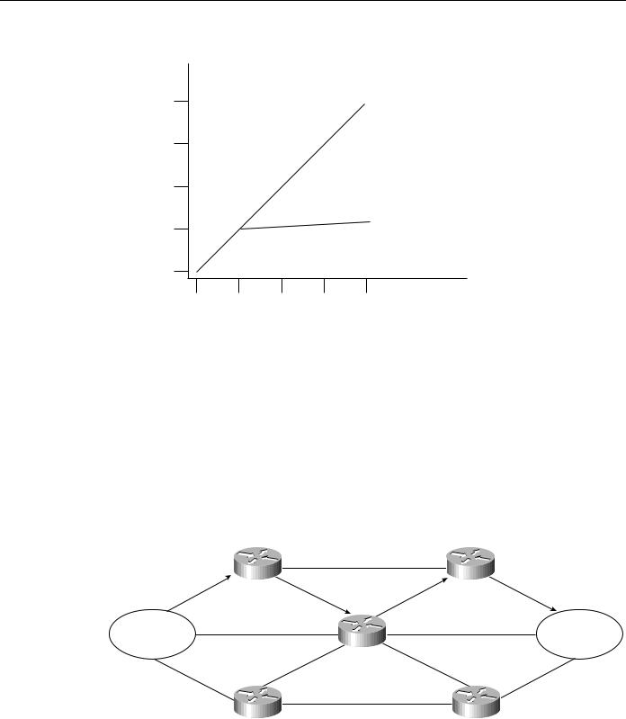
The reduction in route propagation and routing information overhead can be significant. Figure 3-3 illustrates the potential savings. The vertical axis of Figure 3-3 shows the number of routing table entries. The horizontal axis measures the number of subnets. Without summarization, each router in a network with 1,000 subnets must contain 1,000 routes. With summarization, the picture changes considerably. If you assume a Class B network with eight bits of subnet address space, each router needs to know all of the routes for each subnet in its network number (250 routes, assuming that 1,000 subnets fall into four major networks of 250 routers each) plus one route for each of the other networks (three) for a total of 253 routes. This represents a nearly 75-percent reduction in the size of the routing table.
The preceding example shows the simplest type of route summarization: collapsing all the subnet routes into a single network route. Some routing protocols also support route summarization at any bit boundary (rather than just at major network number boundaries) in a network address. A routing protocol can summarize on a bit boundary only if it supports variable-length subnet masks (VLSMs).
Some routing protocols summarize automatically. Other routing protocols require manual configuration to support route summarization, as shown in Figure 3-3.
Designing Large-Scale IP Internetworks 3-3
Implementing Routing Protocols
Figure 3-3 Route summarization benefits.
1000
Without summarization
750
Routing table
entries
500
With summarization
250
0
0 |
250 |
500 |
750 |
1000 |
Number of subnets
Route Selection
Route selection is trivial when only a single path to the destination exists. However, if any part of that path should fail, there is no way to recover. Therefore, most networks are designed with multiple paths so there are alternatives in case a failure occurs.
Routing protocols compare route metrics to select the best route from a group of possible routes. Route metrics are computed by assigning a characteristic or set of characteristics to each physical network. The metric for the route is an aggregation of the characteristics of each physical network in the route. Figure 3-4 shows a typical meshed network with metrics assigned to each link and the best route from source to destination identified.
Figure 3-4 Routing metrics and route selection.
|
Router 1 |
8 |
Router 4 |
|
|
||
5 |
3 |
3 |
1 |
|
|
||
Source |
8 |
|
7 |
|
Router 3 |
Destination |
|
|
|
|
|
6 |
4 |
3 |
5 |
|
|
2 |
|
|
Router 2 |
|
Router 5 |
Routing protocols use different techniques for assigning metrics to individual networks. Further, each routing protocol forms a metric aggregation in a different way. Most routing protocols can use multiple paths if the paths have an equal cost. Some routing protocols can even use multiple paths when paths have an unequal cost. In either case, load balancing can improve overall allocation of network bandwidth.
3-4 Internetwork Design Guide

Convergence
When multiple paths are used, there are several ways to distribute the packets. The two most common mechanisms are per-packet load balancing and per-destination load balancing. Per-packet load balancing distributes the packets across the possible routes in a manner proportional to the route metrics. With equal-cost routes, this is equivalent to a round-robin scheme. One packet or destination (depending on switching mode) is distributed to each possible path. Per-destination load balancing distributes packets across the possible routes based on destination. Each new destination is assigned the next available route. This technique tends to preserve packet order.
Note Most TCP implementations can accommodate out-of-order packets. However, out-of-order packets may cause performance degradation.
When fast switching is enabled on a router (default condition), route selection is done on a perdestination basis. When fast switching is disabled, route selection is done on a per-packet basis. For line speeds of 56 Kbps and faster, fast switching is recommended.
Convergence
When network topology changes, network traffic must reroute quickly. The phrase “convergence time” describes the time it takes a router to start using a new route after a topology changes. Routers must do three things after a topology changes:
•
•
•
Detect the change
Select a new route
Propagate the changed route information
Some changes are immediately detectable. For example, serial line failures that involve carrier loss are immediately detectable by a router. Other failures are harder to detect. For example, if a serial line becomes unreliable but the carrier is not lost, the unreliable link is not immediately detectable. In addition, some media (Ethernet, for example) do not provide physical indications such as carrier loss. When a router is reset, other routers do not detect this immediately. In general, failure detection is dependent on the media involved and the routing protocol used.
Once a failure has been detected, the routing protocol must select a new route. The mechanisms used to do this are protocol-dependent. All routing protocols must propagate the changed route. The mechanisms used to do this are also protocol-dependent.
Network Scalability
The capability to extend your internetwork is determined, in part, by the scaling characteristics of the routing protocols used and the quality of the network design.
Network scalability is limited by two factors: operational issues and technical issues. Typically, operational issues are more significant than technical issues. Operational scaling concerns encourage the use of large areas or protocols that do not require hierarchical structures. When hierarchical protocols are required, technical scaling concerns promote the use of small areas. Finding the right balance is the art of network design.
From a technical standpoint, routing protocols scale well if their resource use grows less than linearly with the growth of the network. Three critical resources are used by routing protocols: memory, central processing unit (CPU), and bandwidth.
Designing Large-Scale IP Internetworks 3-5

Implementing Routing Protocols
Memory
Routing protocols use memory to store routing tables and topology information. Route summarization cuts memory consumption for all routing protocols. Keeping areas small reduces the memory consumption for hierarchical routing protocols.
CPU
CPU usage is protocol-dependent. Some protocols use CPU cycles to compare new routes to existing routes. Other protocols use CPU cycles to regenerate routing tables after a topology change. In most cases, the latter technique will use more CPU cycles than the former. For link-state protocols, keeping areas small and using summarization reduces CPU requirements by reducing the effect of a topology change and by decreasing the number of routes that must be recomputed after a topology change.
Bandwidth
Bandwidth usage is also protocol-dependent. Three key issues determine the amount of bandwidth a routing protocol consumes:
•When routing information is sent—Periodic updates are sent at regular intervals. Flash updates are sent only when a change occurs.
•What routing information is sent—Complete updates contain all routing information. Partial updates contain only changed information.
•Where routing information is sent—Flooded updates are sent to all routers. Bounded updates are sent only to routers that are affected by a change.
Note These three issues also affect CPU usage.
Distance vector protocols such as Routing Information Protocol (RIP), Interior Gateway Routing Protocol (IGRP), Internetwork Packet Exchange (IPX) RIP, IPX Service Advertisement Protocol (SAP), and Routing Table Maintenance Protocol (RTMP), broadcast their complete routing table periodically, regardless of whether the routing table has changed. This periodic advertisement varies from every 10 seconds for RTMP to every 90 seconds for IGRP. When the network is stable, distance vector protocols behave well but waste bandwidth because of the periodic sending of routing table updates, even when no change has occurred. When a failure occurs in the network, distance vector protocols do not add excessive load to the network, but they take a long time to reconverge to an alternative path or to flush a bad path from the network.
Link-state routing protocols, such as Open Shortest Path First (OSPF), Intermediate System- to-Intermediate System (IS-IS), and NetWare Link Services Protocol (NLSP), were designed to address the limitations of distance vector routing protocols (slow convergence and unnecessary bandwidth usage). Link-state protocols are more complex than distance vector protocols, and running them adds to the router’s overhead. The additional overhead (in the form of memory utilization and bandwidth consumption when link-state protocols first start up) constrains the number of neighbors that a router can support and the number of neighbors that can be in an area.
When the network is stable, link-state protocols minimize bandwidth usage by sending updates only when a change occurs. A hello mechanism ascertains reachability of neighbors. When a failure occurs in the network, link-state protocols flood link-state advertisements (LSAs) throughout an area. LSAs cause every router within the failed area to recalculate routes. The fact that LSAs need to be flooded throughout the area in failure mode and the fact that all routers recalculate routing tables constrain the number of neighbors that can be in an area.
3-6 Internetwork Design Guide

Security
Enhanced IGRP is an advanced distance vector protocol that has some of the properties of link-state protocols. Enhanced IGRP addresses the limitations of conventional distance vector routing protocols (slow convergence and high bandwidth consumption in a steady state network). When the network is stable, Enhanced IGRP sends updates only when a change in the network occurs. Like link-state protocols, Enhanced IGRP uses a hello mechanism to determine the reachability of neighbors. When a failure occurs in the network, Enhanced IGRP looks for feasible successors by sending messages to its neighbors. The search for feasible successors can be aggressive in terms of the traffic it generates (updates, queries, and replies) to achieve convergence. This behavior constrains the number of neighbors that is possible.
In WANs, consideration of bandwidth is especially critical. For example, Frame Relay, which statistically multiplexes many logical data connections (virtual circuits) over a single physical link, allows the creation of networks that share bandwidth. Public Frame Relay networks use bandwidth sharing at all levels within the network. That is, bandwidth sharing may occur within the Frame Relay network of Corporation X, as well as between the networks of Corporation X and Corporation Y.
Two factors have a substantial effect on the design of public Frame Relay networks:
•Users are charged for each permanent virtual circuit (PVC), which encourages network designers to minimize the number of PVCs.
•Public carrier networks sometimes provide incentives to avoid the use of committed information rate (CIR) circuits. Although service providers try to ensure sufficient bandwidth, packets can be dropped.
Overall, WANs can lose packets because of lack of bandwidth. For Frame Relay networks, this possibility is compounded because Frame Relay does not have a broadcast replication facility, so for every broadcast packet that is sent out a Frame Relay interface, the router must replicate it for each PVC on the interface. This requirement limits the number of PVCs that a router can handle effectively.
In addition to bandwidth, network designers must consider the size of routing tables that need to be propagated. Clearly, the design considerations for an interface with 50 neighbors and 100 routes to propagate are very different from the considerations for an interface with 50 neighbors and 10,000 routes to propagate. Table 3-1 gives a rough estimate of the number of WAN neighbors that a routing protocol can handle effectively.
Table 3-1 |
Routing Protocols and Number of WAN Neighbors |
|
|
|
|
Routing Protocol |
Number of Neighbors per Router |
|
|
|
|
Distance vector |
|
50 |
|
|
|
Link state |
|
30 |
|
|
|
Advanced distance vector |
30 |
|
|
|
|
Security
Controlling access to network resources is a primary concern. Some routing protocols provide techniques that can be used as part of a security strategy. With some routing protocols, you can insert a filter on the routes being advertised so that certain routes are not advertised in some parts of the network.
Designing Large-Scale IP Internetworks 3-7

Enhanced IGRP Internetwork Design Guidelines
Some routing protocols can authenticate routers that run the same protocol. Authentication mechanisms are protocol specific and generally weak. In spite of this, it is worthwhile to take advantage of the techniques that exist. Authentication can increase network stability by preventing unauthorized routers or hosts from participating in the routing protocol, whether those devices are attempting to participate accidentally or deliberately.
Enhanced IGRP Internetwork Design Guidelines
The Enhanced Interior Gateway Routing Protocol (Enhanced IGRP) is a routing protocol developed by Cisco Systems and introduced with Software Release 9.21 and Cisco Internetworking Operating System (Cisco IOS) Software Release 10.0. Enhanced IGRP combines the advantages of distance vector protocols, such as IGRP, with the advantages of link-state protocols, such as Open Shortest Path First (OSPF). Enhanced IGRP uses the Diffusing Update ALgorithm (DUAL) to achieve convergence quickly.
Enhanced IGRP includes support for IP, Novell NetWare, and AppleTalk. The discussion on Enhanced IGRP covers the following topics:
•
•
•
•
•
•
•
Enhanced IGRP Network Topology
Enhanced IGRP Addressing
Enhanced IGRP Route Summarization
Enhanced IGRP Route Selection
Enhanced IGRP Convergence
Enhanced IGRP Network Scalability
Enhanced IGRP Security
Caution If you are using candidate default route in IP Enhanced IGRP and have installed multiple releases of Cisco router software within your internetwork that include any versions prior to September 1994, contact your Cisco technical support representative for version compatibility and software upgrade information.
Refer to your software release notes for details.
Enhanced IGRP Network Topology
Enhanced IGRP uses a nonhierarchical (or flat) topology by default. Enhanced IGRP automatically summarizes subnet routes of directly connected networks at a network number boundary. This automatic summarization is sufficient for most IP networks. See the section “Enhanced IGRP Route Summarization” later in this chapter for more details.
Enhanced IGRP Addressing
The first step in designing an Enhanced IGRP network is to decide on how to address the network. In many cases, a company is assigned a single NIC address (such as a Class B network address) to be allocated in a corporate internetwork. Bit-wise subnetting and variable-length subnetwork masks (VLSMs) can be used in combination to save address space. Enhanced IGRP for IP supports the use of VLSMs.
Consider a hypothetical network where a Class B address is divided into subnetworks, and contiguous groups of these subnetworks are summarized by Enhanced IGRP. The Class B network 156.77.0.0 might be subdivided as illustrated in Figure 3-5.
3-8 Internetwork Design Guide

Enhanced IGRP Route Summarization
Figure 3-5 Variable-length subnet masks (VLSMs) and route summarization boundaries.
Route summarization boundary
156.77.xxxx yyyy.y zzzzzzz
Subnet mask boundary
In Figure 3-5, the letters x, y, and z represent bits of the last two octets of the Class B network as follows:
•The four x bits represent the route summarization boundary.
•The five y bits represent up to 32 subnets per summary route.
•The seven z bits allow for 126 (128-2) hosts per subnet.
Enhanced IGRP Route Summarization
With Enhanced IGRP, subnet routes of directly connected networks are automatically summarized at network number boundaries. In addition, a network administrator can configure route summarization at any interface with any bit boundary, allowing ranges of networks to be summarized arbitrarily.
Enhanced IGRP Route Selection
Routing protocols compare route metrics to select the best route from a group of possible routes. The following factors are important to understand when designing an Enhanced IGRP internetwork. Enhanced IGRP uses the same vector of metrics as IGRP. Separate metric values are assigned for bandwidth, delay, reliability, and load. By default, Enhanced IGRP computes the metric for a route by using the minimum bandwidth of each hop in the path and adding a media-specific delay for each hop. The metrics used by Enhanced IGRP are as follows:
•Bandwidth—Bandwidth is deduced from the interface type. Bandwidth can be modified with the bandwidth command.
•Delay—Each media type has a propagation delay associated with it. Modifying delay is very useful to optimize routing in network with satellite links. Delay can be modified with the delay command.
•Reliability—Reliability is dynamically computed as a rolling weighted average over five seconds.
•Load—Load is dynamically computed as a rolling weighted average over five seconds.
When Enhanced IGRP summarizes a group of routes, it uses the metric of the best route in the summary as the metric for the summary.
Note For information on Enhanced IGRP load sharing, see the section “SRB Technology Overview and Implementation Issues” in Chapter 4, “Designing SRB Internetworks.”
Designing Large-Scale IP Internetworks 3-9

Enhanced IGRP Internetwork Design Guidelines
Enhanced IGRP Convergence
Enhanced IGRP implements a new convergence algorithm known as DUAL (Diffusing Update ALgorithm). DUAL uses two techniques that allow Enhanced IGRP to converge very quickly. First, each Enhanced IGRP router stores its neighbors’ routing tables. This allows the router to use a new route to a destination instantly if another feasible route is known. If no feasible route is known based upon the routing information previously learned from its neighbors, a router running Enhanced IGRP becomes active for that destination and sends a query to each of its neighbors, asking for an alternative route to the destination. These queries propagate until an alternative route is found. Routers that are not affected by a topology change remain passive and do not need to be involved in the query and response.
A router using Enhanced IGRP receives full routing tables from its neighbors when it first communicates with the neighbors. Thereafter, only changes to the routing tables are sent and only to routers that are affected by the change. A successor is a neighboring router that is currently being used for packet forwarding, provides the least cost route to the destination, and is not part of a routing loop. Information in the routing table is based on feasible successors. Feasible successor routes can be used in case the existing route fails. Feasible successors provide the next least-cost path without introducing routing loops.
The routing table keeps a list of the computed costs of reaching networks. The topology table keeps a list of all routes advertised by neighbors. For each network, the router keeps the real cost of getting to that network and also keeps the advertised cost from its neighbor. In the event of a failure, convergence is instant if a feasible successor can be found. A neighbor is a feasible successor if it meets the feasibility condition set by DUAL. DUAL finds feasible successors by the performing the following computations:
•Determines membership of V1. V1 is the set of all neighbors whose advertised distance to network x is less than FD. (FD is the feasible distance and is defined as the best metric during an
active-to-passive transition.)
•Calculates Dmin. Dmin is the minimum computed cost to network x.
•Determines membership of V2. V2 is the set of neighbors that are in V1 whose computed cost to network x equals Dmin.
The feasibility condition is met when V2 has one or more members. The concept of feasible successors is illustrated in Figure 3-6. Consider Router A’s topology table entries for Network 7. Router B is the successor with a computed cost of 31 to reach Network 7, compared to the computed costs of Router D (230) and Router H (40).
3-10 Internetwork Design Guide
Enhanced IGRP Convergence
Figure 3-6 |
DUAL feasible successor. |
|
|
|||
|
|
Network 2 |
|
|
Network 7 |
|
|
|
|
|
|
|
|
|
|
|
|
|
|
(10) |
|
|
|
|
|
Network 8 |
|
|
|
|
Router H |
|
(20) |
Router G |
|
|
|
|
|
||
|
|
|
|
|
Network 3 |
Network 6 |
|
|
|
|
|
|
|
|
|
|
|
|
FDDI |
|
Network 1 |
|
|
Router B |
|
Dual ring |
Router C |
|
|
|
|
|
|
|
|
|
|
|
|
(1) |
|
(10) |
|
|
(10) |
|
|
(10) |
Router A |
|
|
Network 4 |
Network 5 |
|
|
|
|
|
|
|
||
No.7 |
(31/21) |
B |
Router D |
(100) |
Router E |
Router F |
|
(100) |
|
||||
No.7 (230/220) |
D |
|
|
|
|
|
No.7 |
(40/30) |
H |
|
|
|
|
Net Cost Neighbor (computed/
adv.)
If Router B becomes unavailable, Router A will go through the following three-step process to find a feasible successor for Network 7:
Step 1 Determining which neighbors have an advertised distance to Network 7 that is less than Router A’s feasible distance (FD) to Network 7. The FD is 31 and Router H meets this condition. Therefore, Router H is a member of V1.
Step 2 Calculating the minimum computed cost to Network 7. Router H provides a cost of 40, and Router D provides a cost of 230. Dmin is, therefore, 40.
Step 3 Determining the set of neighbors that are in V1 whose computed cost to Network 7 equals Dmin (40). Router H meets this condition.
The feasible successor is Router H which provides a least cost route of 40 from Router A to Network 7. If Router H now also becomes unavailable, Router A performs the following computations:
Step 1 Determines which neighbors have an advertised distance to Network 7 that is less than the FD for Network 7. Because both Router B and H have become unavailable, only Router D remains. However, the advertised cost of Router D to Network 7 is 220, which is greater than Router A’s FD (31) to Network 7. Router D, therefore, cannot be a member of V1. The FD remains at 31—the FD can only change during an active-to-passive transition, and this did not occur. There was no transition to active state for Network 7; this is known as a local computation.
Step 2 Because there are no members of V1, there can be no feasible successors. Router A, therefore, transitions from passive to active state for Network 7 and queries its neighbors about Network 7. There was a transition to active; this is known as a diffusing computation.
Designing Large-Scale IP Internetworks 3-11
Enhanced IGRP Internetwork Design Guidelines
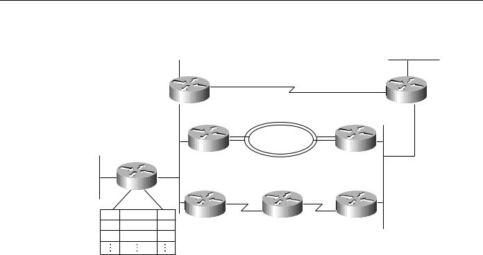
The following example and graphics further illustrate how Enhanced IGRP supports virtually instantaneous convergence in a changing internetwork environment. In Figure 3-7, all routers can access one another and Network N. The computed cost to reach other routers and Network N is shown. For example, the cost from Router E to Router B is 10. The cost from Router E to Network N is 25 (cumulative of 10 + 10 + 5 = 25).
Figure 3-7 DUAL example (part 1): initial network connectivity.
Network N
(5)
Router A
(10)30
|
Router B |
Router C |
|
|
(15) |
25 |
(10) |
(15) |
|
|
(15) |
|
Router E |
Router D |
|
Router E |
|
|
|
40 |
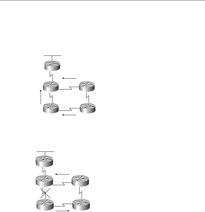
In Figure 3-8, the connection between Router B and Router E fails. Router E sends a multicast query to all of its neighbors and puts Network N into an active state.
Figure 3-8 DUAL example (part 2): sending queries.
Network N
Router A
Router B |
Router C |
Router E |
Router D |
E query
Next, as illustrated in Figure 3-9, Router D determines that it has a feasible successor. It changes its successor from Router E to Router C and sends a reply to Router E.
3-12 Internetwork Design Guide