

Cisco. Fundamentals Network Design - Cisco Press
.pdfSRB Network Design
•Is the network a multiprotocol environment? This question implicitly raises the topic of prioritization. When dealing with a multiprotocol internetwork, you must consider your options for prioritizing traffic to ensure acceptable response time for interactive traffic, while maintaining adequate internetworking resources to handle other types of traffic, such as file transfers.
In general, it is best to design a router network in a hierarchical fashion; there are typically three logical service layers: the backbone (or core) service layer, the distribution service layer, and the access service layer. Figure 4-31 illustrates these basic service layers.
When designing a router network for SRB, consideration should be given to the design of virtual rings. Two key issues affect the design of virtual rings:
•
•
The type of SRB connectivity required (hierarchical, distributed, or flat)
The corporate organizational structure
Figure 4-31 Backbone, distribution, and access service layers in an SRB environment.
|
|
|
WAN backbone |
|
|
Backbone services |
|
|
|
|
|
|
|
Router |
|
Router |
|
|
|
|
Virtual ring 0 |
|
|
|
|
Token |
|
Token |
|
|
|
Ring |
|
Ring |
Central site |
|
|
|
|
|
|
Distribution services |
Router |
Router |
Regional hubs |
Router |
Token |
Ring |
|||||
|
|
|
|
|
3745 |
|
Virtual ring 1 |
Virtual ring 2 |
|
Campus backbone |
|
Branch offices
|
Router |
Router |
Router |
Router |
Access |
Token |
|
|
Token |
services |
Ring |
|
|
Ring |
The remainder of this section focuses on network design approaches that help create scalable networks. The following topics are discussed:
•
•
•
Hierarchical Design for SNA Environments
Hierarchical Design for NetBIOS Environments
Queuing and Prioritization Schemes
Designing SRB Internetworks 4-39
SRB Network Design
Hierarchical Design for SNA Environments
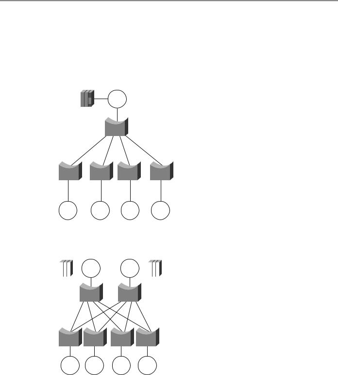
In SNA-only networks, all processing is hierarchical, where a single FEP or a few FEPs (one primary and one secondary) are the target of all remote rings. The SRB topology is focused from all remote rings to a single or a few redundant rings. A topology featuring a single FEP is illustrated in Figure 4-32.
Figure 4-32 Hierarchical topology featuring a single FEP.
Token
Ring
FEP
Token |
Token |
Token |
Token |
Ring |
Ring |
Ring |
Ring |
A topology featuring duplicate FEPs on duplicate rings is illustrated in Figure 4-33.
Figure 4-33 |
Duplicate FEPs on duplicate rings. |
|||||||||
|
|
|
|
|
|
|
|
|
||
|
|
|
|
|
Token |
Token |
|
|
|
|
|
|
|
|
|
|
|||||
|
|
|
|
|
Ring |
Ring |
|
|
|
|
|
|
|
|
|
|
|
|
|
|
|
|
FEP |
|
|
FEP |
||||||
Token |
Token |
Token |
Token |
Ring |
Ring |
Ring |
Ring |
The topology in Figure 4-33 is a partially meshed topology because the remote nodes cannot reach each other; they can reach only the core of the network where the FEPs are located.
When you are designing a partially meshed topology, several options are available. SNA traffic can be generalized as having few explorer packets and having the requirement to connect many remote sites. The suggested topology for a partially meshed topology depends on whether the link speed to
4-40 Cisco CCIE Fundamentals: Network Design
Hierarchical Design for SNA Environments
the core is greater than 64 Kbps. Contact your technical support representative for specific limitations and capabilities regarding the maximum number of peers for the various encapsulation implementations and your specific network attributes.
To scale a partially meshed network to diameters of greater than 15 to 100 remote rings, you can take two approaches: Build a hierarchical structure of virtual rings, or build a scalable partially meshed structure using a single virtual ring.
Proceed with caution to avoid uncontrolled growth in virtual rings, especially in parallel, because parallel virtual rings replicate explorer packets, which results in unnecessary explorer packet traffic.
Scalable Partially Meshed Rings
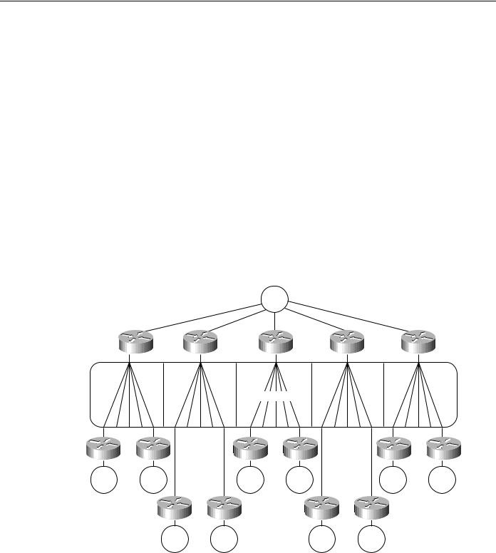
With a partially meshed ring topology, the objective is to leverage the advantage of a network that does not require any-to-any connectivity. You can use a single virtual ring to connect a series of routers at the FEP sites. For each additional 15 to 100 remote peers, you must add a router to the central site. Figure 4-34 illustrates this kind of environment. Contact your technical support representative for more information about specific limitations and recommendations that might apply to your network specifications.
Figure 4-34 Virtual ring environment interconnecting multiple remote peers.
FEP
Ring
No. 1
Single virtual ring
Token |
Token |
|
Token |
Token |
Token |
Token |
Ring |
Ring |
|
Ring |
Ring |
Ring |
Ring |
|
15–30 |
|
|
15–30 |
|
15–30 |
|
remote |
|
|
remote |
|
remote |
|
peers |
|
|
peers |
|
peers |
|
Token |
Token |
|
Token |
Token |
|
|
Ring |
15–30 Ring |
|
Ring |
15–30 Ring |
|
|
|
remote |
|
|
remote |
|
|
|
peers |
|
|
peers |
|
The network illustrated in Figure 4-34 will work for local acknowledgment because all traffic exists on a single virtual ring. A potential problem with this topology is that the number of routers is related to the number of virtual rings, not to the LAN or WAN connectivity at the FEP site. A site with two WAN links and a Token Ring can require several routers if it is the main FEP site.
Designing SRB Internetworks 4-41
SRB Network Design
Hierarchical Virtual Rings
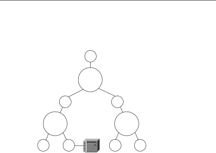
Using hierarchical virtual rings, you can use physical token rings and virtual rings to create a hierarchy of virtual rings. Figure 4-35 illustrates such a hierarchy.
Figure 4-35 Hierarchical virtual ring topology.
FEP
Token Physical
Ring Token Ring
Main virtual ring
|
Token |
Token |
Physical |
|
|
Ring |
Ring |
token rings |
|
|
Area |
|
Area |
|
|
virtual |
|
virtual |
|
|
ring No. 1 |
ring No. n |
|
|
Token |
Token |
Token |
Token |
Physical |
Ring |
Ring |
Ring |
Ring |
token rings |
Cluster controller
Because the destination of all explorer packets is to the core virtual ring, you can use filters to eliminate explorer packet traffic crossing between local-access virtual rings at the point where rings meet. The filters would also filter out FEP traffic. As an alternative, you can use the same virtual ring number for each virtual ring to filter out FEP traffic that might otherwise traverse the local-access virtual rings.
This design is limited in that the hop count might limit Token Ring SRB connectivity. Because the connectivity from access point to FEP uses four hops, additional local bridges at the access points or at the central site might not be reachable from the entire network.
Combined Designs
Networks can be built from hierarchical designs and from scalable partially meshed designs as long as you prevent explorer packet traffic from reexploring access points. To fulfill this requirement, write access lists to prevent explorer packet traffic from entering a ring if that traffic did not originate from the ring that has an FEP.
Hierarchical Design for NetBIOS Environments
The challenge of NetBIOS is that applications might require unrestricted ring-to-ring connectivity. The SRB protocol was not designed to scale, and network designers often demand that routers help scale beyond the original design of the protocol.
4-42 Cisco CCIE Fundamentals: Network Design

Queuing and Prioritization Schemes
Limitations on the maximum number of peers mandates that your only topological option for a NetBIOS SRB network is the hierarchical environment illustrated in Figure 4-35. This design poses certain challenges because of increased explorer packet traffic. It is imperative that you create a single-stream, spanning connection through the network to minimize explorer packets. To succeed, a hierarchical NetBIOS network needs three elements:
•
•
•
Proxy explorer
Aggressive explorer packet caching
NetBIOS name caching
These features allow switching of valid NetBIOS traffic even under the worst conditions of high explorer packet load. You might not be able to use the partially meshed network design if you have to maintain unrestricted ring-to-ring connectivity. Contact your technical support representative to determine any specific limitations for your network topology and design implementation. Refer to the “Explorer Packets and Propagation” and “NetBIOS Broadcast Handling” sections earlier in this chapter for additional details concerning these topics.
Queuing and Prioritization Schemes
The following information focuses on current prioritization mechanisms. Prioritization tools discussed include:
•
•
•
•
•
Priority Queuing
Custom Queuing
SAP Prioritization
Enhanced LU Address Prioritization
SAP Filters on WAN Links
Note The queuing and prioritization schemes described in this section rely on process switching. If the router is configured for fast switching or for autonomous switching, the configuration of a queuing or prioritization scheme will increase processor utilization. However, increased processor utilization is usually not a problem when the router is sending traffic over low-speed WAN links.
Priority Queuing
Priority queuing (introduced in Software Release 9.1) allows packets to be prioritized. When priority queuing is enabled on an interface, the router maintains up to four output queues for that interface. During congestion, the packets are placed in one of the four queues according to their priority. The router services all packets on the highest priority queue before moving on to the next highest priority queue. In other words, the queuing delay of a packet on a lower priority queue is nondeterministic: An RSRB session set to normal priority might time out if, for example, IPX packet traffic is heavy and is configured for the highest priority queue.
This scheme introduces a problem in that packets configured for lower priority queues might not be serviced in a timely manner, or at all, depending on the bandwidth used by packets sent from the higher priority queues. Priority queuing does not provide bandwidth allocation.
Priority queuing can be used when there is sufficient bandwidth to accommodate all packets destined for a particular interface, but where packets from certain protocols such as file transfers cause other protocols such as Telnet sessions to suffer from poor response.
Designing SRB Internetworks 4-43

SRB Network Design
If there is insufficient bandwidth on an output interface to pass data from various sources, priority queuing cannot solve the limited bandwidth condition. If there is not enough bandwidth to pass all of the data destined for an interface, protocols assigned to the lower priority queues suffer packet loss.
Priority queuing introduces processor overhead that might be acceptable for slow interfaces, but might be unacceptable for higher speed interfaces such as Ethernet, Token Ring, or FDDI. If you are currently fast switching packets, be aware that priority queuing requires that these packets be process switched, which would negatively impact performance.
Use the priority-list global configuration command to define priority lists and the priority-group interface command to assign a list to an interface. Priority queuing can be configured instead of, but not in addition to, custom queuing.
Note Priority queuing does not operate over X.25.
Custom Queuing
Custom queuing (introduced in Software Release 9.21 and enhanced in Cisco IOS Software Release 11.0) allows you to allocate a percentage of bandwidth to a particular kind of traffic when the available bandwidth is unable to accommodate the aggregate traffic queued.
When custom queuing is enabled on an interface, the router maintains 16 output queues (numbered from 0 to 15) for that interface that can be used to modify queuing behavior. The router cycles through queue numbers 1 to 15 in a sequential fashion, delivering packets in the current queue before moving on to the next. Associated with each output queue is a configurable byte count, which specifies how many bytes of data should be delivered from the current queue by the router before the router moves on to the next queue.When a particular queue is being processed, packets are sent until the number of bytes sent exceeds the queue byte count or the queue is empty.
Queue number 0 is a system queue; its queue is emptied before any of the queues numbered 1 to 15 are processed. The router queues high priority packets to this queue, such as interface keepalive packets. Routing protocol packets are not automatically placed in the system queue.
The custom queuing implementation should not impact the performance of existing packet queuing code. The queuing algorithm implementation is time-critical because it affects packet delivery time when custom queuing is in use.
When custom queuing (or priority queuing) is enabled, it should take much longer for the router to switch packets because each packet has to be classified by the processor card.
Use the queue-list global configuration command to define custom queue lists and the custom-queue-list interface configuration command to assign a custom queue list to an interface. Custom queuing can be configured instead of, but not in addition to, priority queuing.
Figure 4-36 describes the syntax of the priority-list and queue-list commands.
Note Custom queuing does not operate over X.25.
4-44 Cisco CCIE Fundamentals: Network Design

Queuing and Prioritization Schemes
Figure 4-36
Command
priority-list or queue-list
Priority and custom queuing command syntax.
List |
|
Protocol |
Queue |
||
|
|
|
Priority |
Custom |
|
|
|
apollo |
|
|
|
1 |
|
appletalk |
|
1 |
|
2 |
|
bridge |
|
||
|
|
2 |
|||
3 |
|
chaos |
|
||
|
high |
3 |
|||
4 |
|
decnet |
|||
|
. |
||||
5 |
|
ip |
medium |
||
protocol |
. |
||||
6 |
ipx† |
normal |
|||
|
. |
||||
7 |
|
pup |
low |
||
|
14 |
||||
8 |
|
rsrb |
|
||
|
|
15 |
|||
9 |
|
stun |
|
||
|
|
16 |
|||
10 |
|
vines |
|
||
|
|
|
|||
xns
† In releases prior to Cisco IOS 10.0, the protocol argument is “novell”.
*Applies only to AppleTalk, bridging, IP, IPX, VINES, and XNS.
Optional arguments
list |
access-list* |
lt |
byte-count |
gt |
byte-count |
tcp |
port-number |
udp |
port-number |
bridge list |
access-list |
SAP Prioritization
The purpose of the SAP prioritization feature is to allow you to specify the priority (precedence and bandwidth) of a protocol over another protocol across the RSRB/SDLLC WAN. The prioritization is based on the destination service access point (DSAP) address and source service access point (SSAP) address.
SAP prioritization can be built based on priority queuing or on custom queuing. The actual SAP classification code can be developed regardless of the underlying prioritization mechanism. The priority queuing mechanism addresses only the precedence criteria. The custom queuing mechanism provides precedence and guarantees bandwidth. This section describes SAP prioritization using priority queuing.
To provide a fine granularity in the prioritization of packets, the sap priority-list global configuration command (available in Software Release 9.1[9]) allows you to specify any combination of DSAP, SSAP, destination MAC (DMAC) address, and source MAC (SMAC) address.
For example, if you want to prioritize all SNA traffic (SAP 04) over NetBIOS traffic (SAP F0), only the DSAP or SSAP must be configured. In contrast, if you want to give precedence to traffic on a particular LLC2 session, you must specify four parameters: DSAP address, SSAP address, DMAC address, and SMAC address. Use the sap-priority list interface configuration command (available in Software Release 9.1[9]) to tie the priority list to a particular input interface.
You must also specify the priority option in the source-bridge remote-peer global configuration command to enable SAP prioritization. In addition, you must configure the priority-list global configuration command for the appropriate interfaces and use the priority-group interface configuration command on the output interface.
Enhanced LU Address Prioritization
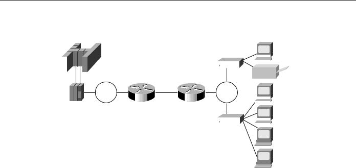
The enhanced logical unit (LU) address-prioritization feature allows you to specify the physical unit (PU) on which an LU resides. This is important because multiple PUs on a Token Ring or on a multidropped SDLC line might have LUs with the same LU address. For example, Figure 4-37 illustrates a situation in which LU02 on 3174-2 is a 3287 printer, and LU02 on 3174-1 is a 3278 terminal. It is undesirable to assign the same priority to the printer and the terminal.
Designing SRB Internetworks 4-45
SRB Network Design
Figure 4-37 |
|
LU prioritization for RSRB. |
|
|
|
|
|
|
|
|
|
|||||||||||||
|
|
IBM 3090 |
|
|
|
|
|
|
|
|
|
|
|
|
|
|
|
|||||||
|
|
|
|
|
|
|
|
|
|
|
|
|
|
|
|
3174-2 |
|
|
LU03 |
|||||
|
|
|
|
|
|
|
|
|
|
|
|
|
|
|
|
|
|
|||||||
|
|
|
|
|
|
|
|
|
|
|
|
|
|
|
|
|
|
|||||||
|
|
|
|
|
|
|
|
|
|
|
|
|
|
|
|
|
||||||||
|
|
|
|
|
|
|
|
|
|
|
|
|
|
|
|
|
|
LU02 |
||||||
|
|
|
|
|
|
|
|
|
|
|
|
|
|
|
|
|
|
|
|
|
|
|
|
|
|
|
|
|
|
|
|
|
|
|
|
|
|
|
|
|
|
|
|
|
|
|
|
|
|
|
|
|
|
|
|
|
|
|
|
|
|
|
|
|
|
|
|
|
|
|
|
|
|
|
|
|
|
|
|
|
|
|
|
|
|
|
|
|
|
|
|
|
|
|
|
|
|
|
|
|
|
|
|
|
|
|
|
|
|
|
|
|
|
|
|
|
|
|
|
|
|
|
|
|
|
|
|
|
|
|
|
|
|
Token |
|
|
|
|
|
|
|
Token |
|
LU05 |
|||||
|
|
|
|
|
|
|
|
|
|
|
|
|
|
|
||||||||||
|
|
|
|
|
|
|
|
|
Ring |
|
Router |
IP |
|
Router |
|
|
Ring |
|
||||||
|
|
|
|
|
|
|
|
|
|
|
|
|
|
|
|
|
|
|
|
|
|
|||
|
FEP |
|
|
|
|
Network |
|
|
|
|
|
|
|
|
|
|
|
LU04 |
||||||
|
|
|
|
|
|
|
|
|
|
|
|
|
|
|
|
|||||||||
|
|
|
|
|
|
|
|
|
|
|
|
|
|
|
|
|
|
|
|
|
|
|
|
|
|
|
|
|
|
|
|
|
|
|
|
|
|
|
|
|
|
|
|
|
|
|
|
|
|
|
|
|
|
|
|
|
|
|
|
|
|
|
|
|
|
|
|
|
|
|
|
|
|
|
3174-1
LU03
LU02
As of Software Release 9.1(9), the LU address prioritization for both RSRB and serial tunneling (STUN) allow you to prioritize the following addresses in addition to the LU address:
•In the RSRB case, you can specify the MAC and SAP address, which together uniquely identify a PU.
•In the STUN case, you can specify the SDLC address to identify a PU on a multidropped SDLC line.
SAP Filters on WAN Links
SAP filters, which are currently available for serial, Token Ring, and Ethernet interfaces, can be used to prevent local NetBIOS and other broadcasts from traversing the RSRB/SDLLC WAN. To implement SAP filter logic on the RSRB/SDLLC WAN interface, it is desirable to place the code at the RSRB level independent from the encapsulation type on the interface. The same filter code should work for direct HDLC encapsulation, TCP/IP encapsulation, and FST encapsulation. In addition to filtering by SAP address, SAP filters can also be used to filter packets by NetBIOS name.
The commands, which are available in Software Release 9.1.(9), are the same as those used for SRB on the Token Ring interface:
•The access-list list global configuration command builds the access list.
•The rsrb remote-peer ring-group interface configuration command filters by Local Service Access Point (LSAP) address or by NetBIOS station name on the RSRB WAN interface.
•The netbios access-list host global configuration command builds a NetBIOS access filter by host name.
SRB Design Checklist
Before implementing a source-route bridging (SRB) network, be sure to familiarize yourself with the technical reference material in the Router Products Configuration Guide and the Router Products Command Reference publications that deals with SRB internetworking.
4-46 Cisco CCIE Fundamentals: Network Design

Summary
Next, read the “Multiport Bridging” through “WAN Framing” sections earlier in this chapter. Depending on your implementation, you should review the “IP Routing Protocol Selection for SRB Networks” and “SRB Network Design” sections earlier in this chapter. If you require more than eight routers, continue as follows:
Step 1 Evaluate the following requirements:
•Determine which protocols are to be used. Relevant options are hierarchical Systems Network Architecture (SNA) and NetBIOS. If you are running hierarchical SNA, determine the link speeds to the core front end processor (FEP) sites.
•Determine whether parallel paths exist in the network either between individual routers or in the general network. If they do, refer to the “WAN Parallelism” section earlier in this chapter.
•Determine whether the network requires greater than 2-kilobyte frames to be sent across WAN links. If so, refer to the “WAN Frame Sizes” section earlier in this chapter.
Step 2 If the access ring and the FEP-connected sites exceed 15 token rings, you must address the following issues:
•Determine whether local acknowledgment is a requirement. Refer to the “Local Acknowledgment Recommendations” section earlier in this chapter.
•Select an encapsulation method. Refer to the “WAN Framing” section.
•Design a network topology incorporating the rules outlined in the “SRB Network Design” section.
•Select a routing protocol described in the “WAN Parallelism” and “IP Routing Protocol Selection for SRB Networks” sections.
Step 3 If performance is important for your internetwork, review the “IP Routing Protocol
Selection for SRB Networks” section.
Step 4 Prepare each router’s configuration for the following:
•SRB (Refer to the “Explorer Packets and Propagation” and “WAN Framing” sections.)
•IP route tuning (Refer to the “IP Routing Protocol Selection for SRB Networks” section.)
Step 5 Turn on proxy explorer as needed. Refer to the “Explorer Packets and Propagation” section.
Step 6 If the network requires NetBIOS, proceed as follows:
•Turn on NetBIOS name caching.
•Limit the explorer packet processing queue to 20 entries. Refer to the “Explorer Packets and Propagation” section.
Step 7 If you expect to exceed 250 Token Rings, contact your technical support representative for additional information.
Summary
This chapter discussed source-route bridging (SRB) and remote source-route bridging (RSRB). It addressed the challenges of this environment and helped network designers successfully implement SRB within a large, multiprotocol topology, including covering the following areas:
Designing SRB Internetworks 4-47

Summary
•SRB technology and implementation overview
•Internet Protocol (IP) routing protocol selection and implementation
•SRB network design recommendations and guidelines
4-48 Cisco CCIE Fundamentals: Network Design