

Cisco. Fundamentals Network Design - Cisco Press
.pdfExample of APPN/CIP in a Sysplex Environment
Figure 6-27 Subarea to APPN migration—phase five.
Data Center 1 |
|
Data Center 2 |
||||||||||||||||||||||||
|
|
|
|
|
|
|
|
|
|
|
|
|
|
|
|
|
|
|
|
|
|
|
|
|
|
|
|
|
|
|
|
|
|
|
|
|
|
|
|
|
|
|
|
|
|
|
|
|
|
|
|
|
|
|
|
|
|
|
|
|
|
|
|
|
|
|
|
|
|
|
|
|
|
|
|
|
|
|
|
|
|
|
|
|
|
|
|
|
|
|
|
|
|
|
|
|
|
|
|
|
|
|
|
|
|
|
|
|
|
|
|
|
|
|
|
|
|
|
|
|
|
|
|
|
|
|
|
|
|
|
|
|
|
|
|
|
|
|
|
|
|
|
|
|
|
|
|
|
|
|
|
|
|
|
|
|
|
|
|
|
|
|
|
|
|
|
|
|
|
|
|
|
|
|
|
|
|
|
|
|
|
|
|
|
|
|
|
|
|
|
|
|
|
|
|
|
|
|
|
|
|
|
|
|
|
|
|
|
|
|
|
|
|
|
|
|
|
|
|
|
|
|
|
|
|
|
|
|
|
|
|
|
|
|
|
|
|
|
|
|
|
|
|
|
|
|
|
|
|
|
|
|
|
|
|
|
|
|
|
|
|
|
|
|
|
|
|
|
|
|
|
|
|
|
|
|
|
|
|
|
|
|
|
|
|
|
|
|
|
|
|
|
|
|
|
|
Token |
NN |
NN |
Token |
|
|
||
Ring |
|
|
Ring |
|
APPN |
APPN |
|
NN |
DLUR |
DLUR |
NN |
X25 |
mac 1 |
|
|
mac 2 |
mac 1 |
|
|
mac 2 |
|
|
|
|
|
|
|
||
|
|
|
|
|
|
|
|
|
|
|
||||||
Token |
|
Token |
|
|
|
|
|
|
|
|||||||
|
Ring |
|
|
Ring |
|
|
|
|
|
|
|
|
||||
|
|
|
|
|
|
|
|
|
|
|
||||||
|
|
|
|
|
|
|
|
|
|
|
|
|
|
|
|
|
|
|
|
|
|
|
|
|
|
|
|
|
|
|
|
|
|
|
|
|
|
|
|
|
|
|
|
|
|
|
|
|
|
|
|
|
|
|
|
|
|
|
|
|
|
|
|
|
|
|
|
|
|
|
|
|
|
|
|
|
|
|
|
|
|
|
|
|
Regional Offices
|
|
|
|
|
|
|
|
|
|
|
|
|
|
|
|
|
|
|
|
|
|
|
|
PU 2.0 |
PU 2.0 |
|
PU 2.0 |
||||||||
Example of APPN/CIP in a Sysplex Environment
This section examines APPN and the CIP routers in a Sysplex (system complex) environment. It provides an overview of the Sysplex environment and its relationship with APPN along with a description of how to use the following three approaches to support the Sysplex environment:
•
•
•
Sysplex with APPN Using Subarea Routing—Option One
Sysplex Using Subarea/APPN Routing—Option Two
Sysplex Using APPN Routing—Option Three
It also describes how APPN provides fault tolerance and load sharing capabilities in the data center.
Sysplex Overview
Sysplex provides a means to centrally operate and manage a group of multiple virtual storage (MVS) systems by coupling hardware elements and software services. Many data processing centers have multiple MVS systems to support their business, and these systems often share data and applications. Sysplex is designed to provide a cost-effective solution to meet a company’s expanding requirements by allowing MVS systems to be added and managed efficiently.
A Sysplex environment consists of multiple 9672 CMOS processors, and each CMOS processor presents a VTAM domain. The concept of multiprocessors introduces a problem. Today, users are accustomed to single images. For example, IMS (Information Management System) running on the
Designing APPN Internetworks 6-45

Configuration Examples
mainframe can serve the entire organization on a single host image. With the multiprocessor concept, you would not want to instruct User A to establish the session with IMS on System A and User B to establish the session with IMS on System B because IMS might run on either system.
To resolve this, a function called generic resource was created. The generic resource function enables multiple application programs, which provide the same function, to be known and accessed by a single generic name. This means that User A might sometimes get IMS on System A, and sometimes get IMS on System B. Because both systems have access to the same shared data in the Sysplex, this switching of systems is transparent to the users. VTAM is responsible for resolving the generic name and determining which application program is used to establish the session. This function enables VTAM to provide workload balancing by distributing incoming session initiations among a number of identical application programs that are running on different processors.
Generic resource runs only on VTAM with APPN support. In order to achieve session load balancing across the different processors, users must migrate VTAM from subarea SNA to APPN. The rest of this section examines three options for supporting the Sysplex environment.
Sysplex with APPN Using Subarea Routing—Option One
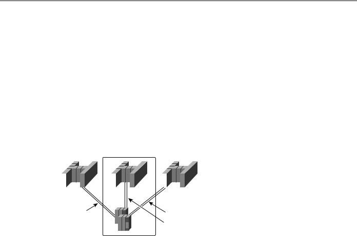
The first option to support the Sysplex environment is to convert the CMC host to a composite network node. Traditionally, the CMC host was the VTAM that owned all of the network’s SNA resources. With this approach, the composite network node is used to describe the combination of VTAM and Network Control Program (NCP). This means that VTAM and NCP function together as a single network node. In Figure 6-28, the CMC host and the FEPs are configured as the composite network node.
Figure 6-28 CMC composite network node with subarea routing—option one.
Migration data |
|
|
CMC |
|
|
Migration data |
|||||||||||
|
|
host A |
|
|
|
|
|
|
|
|
host B |
||||||
|
|
|
|
|
|
|
|
|
|
|
|
|
|
|
|
|
|
|
|
|
|
|
|
|
|
|
|
|
|
|
|
|
|
|
|
|
|
|
|
|
|
|
|
|
|
|
|
|
|
|
|
|
|
|
|
|
|
|
|
|
|
|
|
|
|
|
|
|
|
|
|
|
|
|
|
|
|
|
|
|
|
|
|
|
|
|
|
|
|
|
|
|
|
|
|
|
|
|
|
|
|
|
|
|
|
|
|
|
|
|
|
|
|
|
|
|
|
|
|
|
|
|
|
|
|
CMOS |
CMOS |
CMOS |
FID4 |
|
FID4 |
Composite network node
The VTAM CMC host owns the FEPs. Each FEP is connected to the 9672 CMOS processors through a parallel channel. Each 9672 CMOS processsor is configured as a migration data host and maintains both an APPN and subarea appearance.
Each migration data host establishes subarea connections to the FEPs using Virtual Route Transmission Group (VRTG), which allows APPN to be transported over traditional subarea routing. CP-CP sessions between the CMC host and the 9672 migration data hosts are established using VRTG. Generic resource function is performed in APPN, but all routing is subarea routing. This is the most conservative way to migrate to a Sysplex.
6-46 Cisco CCIE Fundamentals: Network Design
Example of APPN/CIP in a Sysplex Environment
The disadvantage of this approach is that using subarea routing does not provide dynamic implementation of topology changes in APPN, which is available with APPN connection. If you need to add a CMOS processor, subarea PATH changes to every subarea node are required. Another drawback of this approach is that running APPN over subarea routing introduces complexity to your network.
Sysplex Using Subarea/APPN Routing—Option Two
The second option to support the Sysplex environment is to use subarea/APPN routing. This approach is similar to Option One, which was described in the preceding section. With this second approach, the CMC host and the FEPs are converted to a composite network node, as shown in Figure 6-29.
Figure 6-29 CMC composite network node with APPN routing—option two.
|
|
EN A |
|
|
|
|
CMC |
|
|
|
|
EN B |
|
|||
|
|
|
|
|
|
|
|
|
|
|
|
|
|
|
|
|
|
|
|
|
|
|
|
|
|
|
|
|
|
|
|
|
|
|
|
|
|
|
|
|
|
|
|
|
|
|
|
|
|
|
|
|
|
|
|
|
|
|
|
|
|
|
|
|
|
|
|
|
|
|
|
|
|
|
|
|
|
|
|
|
|
|
|
|
|
|
|
|
|
|
|
|
|
|
|
|
|
|
|
|
|
|
|
|
|
|
|
|
|
|
|
|
|
|
|
|
|
|
CMOS |
CMOS |
CMOS |
FID2
FID2
FID4
Composite network node
As shown in Figure 6-29, the two 9672 CMOS processors are converted to pure end nodes (EN A and EN B). APPN connections are established between the 9672s and the FEPs. Sessions come into the CMC in the usual way and the CMC does subarea/APPN interchange function. This means that sessions are converted from subarea routing to APPN routing on the links between the FEPs and the 9672s.
A disadvantage of this second approach is that it performs poorly because the FEPs must perform an extra conversion. This approach also requires more NCP cycles and memory. Although this is very easy to configure and it does not require any changes to the basic subarea routing, the cost of the NCP upgrades can be expensive.
Sysplex Using APPN Routing—Option Three
The third option to support the Sysplex environment is to use APPN routing. With this approach, you use DLUR as a front end to the CMC-owned logical units. Figure 6-30 illustrates this configuration.
Designing APPN Internetworks 6-47

Configuration Examples
Figure 6-30 Sysplex with DLUR using CIP—option three.
EN A |
|
|
|
|
CMC |
|
|
|
|
EN B |
|
|||
|
|
|
|
|
|
|
|
|
|
|
|
|
|
|
|
|
|
|
|
|
|
|
|
|
|
|
|
|
|
|
|
|
|
|
|
|
|
|
|
|
|
|
|
|
|
|
|
|
|
|
|
|
|
|
|
|
|
|
|
|
|
|
|
|
|
|
|
|
|
|
|
|
|
|
|
|
|
|
|
|
|
|
|
|
|
|
|
|
|
|
|
|
|
|
|
|
|
|
|
|
|
|
|
|
CMOS |
CMOS |
CMOS |
FID2 |
|
FID2 |
Router

 Router


DLUR
As shown in Figure 6-30, this is a pure APPN network with APPN routing only. Each CMOS end-node processor is attached to the DLUR routers through APPN. Note that the DLUR routers could be remote and not directly next to the mainframe computers (for example, there could be intervening routers).
This is the preferred approach for implementing the Sysplex environment for the company used in this sample scenario. The following section provides more details on this sample implementation.
The Company’s Network
The company used in this example has a very large IP backbone and a very large SNA network. Today, its multiprotocol and SNA network are separate. The company’s goal is to consolidate the traffic across the multiprotocol Internet. The company has chosen IP as its strategic backbone protocol of choice. To transport the SNA traffic, DLSw+ is used.
In the data center, the company plans to support five different IBM Sysplex environments. Its objective is to have the highest degree of redundancy and fault tolerance. The administrators decided not to run APPN throughout their existing multiprotocol network but chose APPN in the data center to provide the required level of redundancy.
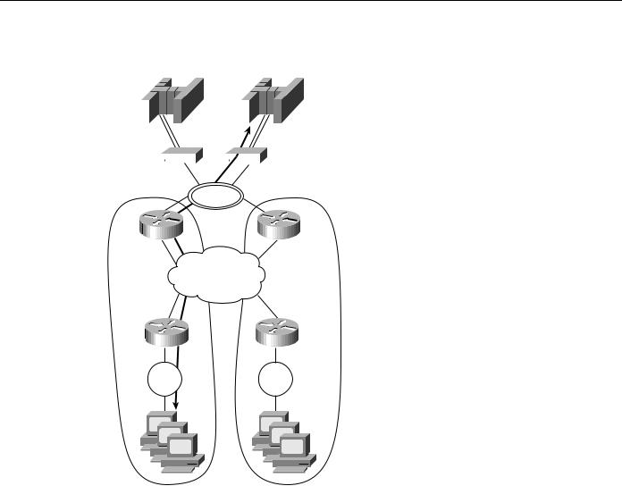
Figure 6-31 shows the configuration of the company’s data center. The diagram on the top right in this figure is a logical view of one Sysplex environment and how it is connected to the multiprotocol network through the CIP/CSNA routers and the APPN routers. Each CIP/CSNA router has two parallel channel adapters to each Sysplex host (Sysplex 1 and Sysplex 2) through separate ESCON Directors. To meet the company’s high availability requirement, this configuration has no single points of failure.
6-48 Cisco CCIE Fundamentals: Network Design

Example of APPN/CIP in a Sysplex Environment
Figure 6-31 Example of APPN in the data center.
|
|
|
Sysplex 1 |
Sysplex 2 |
|||||
|
|
|
|
|
|
|
|
|
|
|
|
|
|
|
|
|
|
|
|
|
|
|
|
|
|
|
|
|
|
|
|
|
|
|
|
|
|
|
|
|
|
|
|
|
|
|
|
|
|
|
|
|
|
|
|
|
|
|
|
|
|
|
|
|
|
|
|
|
|
|
|
|
|
|
|
|
|
|
|
|
|
|
|
|
|
|
|
|
|
|
|
|
|
|
|
|
|
|
|
|
|
|
|
|
|
|
|
|
|
|
|
|
|
|
|
|
|
|
|
CIP/CSNA |
Router |
Router CIP/CSNA |
|
|
|
FDDI |
|
Router |
|
|
|
Router |
|
|
|
Router |
Router |
|
|
|
|
||
APPN router |
|
Router |
WAN routers |
NN/DLUR DLSw+ |
|
Router |
|
|
|
|
|
|
|
Multiprotocol |
|
|
|
Internet |
|
|
|
Router |
DLSw+ |
|
|
|
|
|
|
Token |
|
|
|
Ring |
|
|
Legacy SNA devices |
|
|
Sysplex
DLUS
ENA ENB NNA NNB
9032 |
9032 |
CIP1 CSNA |
CIP2 CSNA |
NN1 DLUR |
|
NN2 DLUR |
|
|
|
In each Sysplex environment, there are a minimum of two network nodes per Sysplex acting as a DLUS. VTAM NNA is designated as the primary DLUS node. NNB is designated the backup DLUS. The remaining hosts are data hosts configured as end nodes. These end node data hosts use NNA as the network-node server.
There are two CIP routers to support every Sysplex environment and at least two APPN routers running DLUR to provide boundary functions support for remote devices. The traffic is expected to load share across the two CIP routers. Consequently, APPN provides load balancing and redundancy in this environment.
Sample Configuration
From an APPN standpoint, NNA in Figure 6-31 can be configured as the primary DLUS. NNB can be configured as the backup DLUS. The following is a configuration example for NN1. NN2 would be configured similarly.
!
appn control-point CISCONET.NN1 dlus CISCONET.NNA
backup-dlus CISCONET.NNB dlur
complete
Designing APPN Internetworks 6-49

Configuration Examples
When the primary DLUS host goes out of service for any reason, the DLUR node is disconnected from its serving DLUS. The DLUR node retries the DLUS/DLUR pipe with NNA. If unsuccessful, it tries its backup DLUS.
To achieve load balancing, every DLUR router defines two parallel APPN transmission groups with equal weights to every VTAM host using the following configuration:
!
!Link to VTAM ENA via CIP router 1
appn link-station LINK1ENA port FDDI0
lan-dest-address 4000.3000.1001 complete
!Link to VTAM ENA via CIP router 2
appn link-station LINK2ENA port FDDI0
lan-dest-address 4000.3000.2001 complete
!Link to VTAM ENB via CIP router 1
appn link-station LINK1ENB port FDDI0
lan-dest-address 4000.3000.1002 complete
!Link to VTAM ENB via CIP router 2
appn link-station LINK2ENB port FDDI0
lan-dest-address 4000.3000.2002 complete
!Link to Primary DLUS NNA via CIP router 1
appn link-station LINK1NNA port FDDI0
lan-dest-address 4000.3000.1003 complete
!Link to Primary DLUS NNA via CIP router 2
appn link-station LINK2NNA port FDDI0
lan-dest-address 4000.3000.2003 complete
!Link to Backup DLUS NNB via CIP router 1
appn link-station LINK1NNB port FDDI0
lan-dest-address 4000.3000.1004 complete
!Link to Backup DLUS NNB via CIP router 2
appn link-station LINK2NNB port FDDI0
lan-dest-address 4000.3000.2004 complete
6-50 Cisco CCIE Fundamentals: Network Design

Example of APPN/CIP in a Sysplex Environment
As shown in the preceding configuration, NN1 defines two APPN transmission groups to ENA, ENB, NNA and NNB. There are two channel attachments to each host and each attachment is connected to separate hardware (for example, a CIP card, CIP router, ESCON Director). Reasons to have duplicate hardware include provision for the loss of any physical component; if this happens the host is still accessible using the alternative path.
From an APPN perspective, there are two transmission groups that connect a DLUR router and every host. One transmission group traverses CIP Router 1 and the other traverses CIP Router 2. When one path fails, the APPN transmission group becomes inoperative. The second transmission group provides an alternative route for host connection through the other path.
All the subarea SSCP/PU and SSCP/LU sessions flow on one of the transmission groups between the DLUR router and the primary DLUS host. As for the LU-LU sessions, the two possible routes between the DLUR router and a VTAM host are available. The DLUR router and a VTAM host select one of these two routes at random for the LU-LU sessions. This randomization provides a certain amount of load distribution across the two CIP routers, although it might not necessarily be statistically load balanced.
There are multiple DLUR routers that support downstream SNA devices. The following is a sample configuration for DLUR router NN1:
source-bridge ring-group 100
dlsw local-peer peer-id 172.18.3.111 promiscuous
!
interface FDDI0
ip address 172.18.3.111 255.255.255.0
!
appn control-point NETA.NN1 complete
!
appn port VDLC1 vdlc vdlc 100 4000.1000.2000 complete
The following is a sample configuration for DLUR router NN2:
source-bridge ring-group 200
dlsw local-peer peer-id 172.18.3.112 promiscuous
!
interface FDDI0
ip address 172.18.3.112 255.255.255.0
!
appn control-point NETA.NN2 complete
!
appn port VDLC2 vdlc vdlc 200 4000.1000.2000 complete
A workstation gains access to the host through the DLUR router. A workstation defines 4000.1000.2000 as the destination MAC address in the emulation software. This virtual MAC address is defined to every DLUR router. When initiating a connection, a workstation sends an all-routes broadcast Test command frame to the MAC address to which it wants to connect. The remote DLSw+ router sends an explorer frame to its peers. Both NN1 and NN2 respond with ICANREACH. The DLSw+ router is configured to use the load balancing mode. This means that the DLSw+ router caches both NN1 and NN2 as peers that can reach the host. Host sessions are established through NN1 and NN2 in a round robin fashion. This allows the company to spread its SNA traffic over two or more DLUR routers. If NN1 becomes unavailable, sessions that traverse NN1 are disruptive but they can be re-established through NN2 with negligible impact.
Designing APPN Internetworks 6-51

Configuration Examples
This design increases overall availability by using duplicate virtual MAC address on the DLUR router. The dual paths provide the option for a secondary path to be available for use when the primary path is unavailable. Another advantage is that this design allows for easy scaling. For example, when the number of SNA devices increases, buffer memory might become a constraint on the DLUR routers. The company can add a DLUR router to support the increased session load. This topology change does not require any network administration from any remote routers or the data center routers.
Example of APPN with FRAS BNN
This section describes the design considerations when building a large enterprise APPN network. It lists the current technologies that allow the company in this example to build a large APPN network. Each option is discussed in detail. FRAS BNN is chosen as an interim scalability solution to reduce the number of network nodes in the network. This allows the network to scale to meet the company’s expanding requirements.
In this example, a government agency has a network that consists of one data center and approximately 100 remote sites. Within the next few years, its network is expected to increase to 500 remote sites.
Figure 6-32 shows a simplified version of the agency’s current APPN network.
Figure 6-32 Sample APPN network for a government agency.
NN/DLUS & EN |
|
|
EN or LEN |
||||||||||||||||||
|
|
|
|
|
|
|
|
|
|
|
|
|
|
|
|
|
|
|
|
|
Company A |
|
|
|
|
|
|
|
|
|
|
|
|
|
|
|
|
|
|
|
|
|
|
|
|
|
|
|
|
|
|
|
|
|
|
||||||||||
|
|
|
|
|
|
|
|
|
|
|
|
||||||||||
IBM |
|
|
|
|
|
|
|
|
|
|
|
|
|
|
|
|
|
|
|
|
Company B |
|
|
|
|
|
|
|
|
|
|
|
|
|
|
|
|
|
|
|
|
Company C |
|
|
|
|
|
|
|
|
|
|
|
||||||||||||
|
|
|
|
|
|
|
|
|
|
|
|
|
|
|
|
|
|
|
|
|
|
|
|
|
|
|
|
|
|
|
|
|
|
|
|
|
|
|
|
|
|
|
|
|
|
|
|
|
|
|
|
|
|
|
|
|
|
|
|
|
|
|
|
|
|
|
FDDI |
NN1 Router |
Router NN2 |
Frame Relay
LU-LU session

 Router
 NN3
NN3
Token
Ring
EN3A
EN3B
6-52 Cisco CCIE Fundamentals: Network Design

Example of APPN with FRAS BNN
The data center consists of 20 mainframe processors from IBM and a variety of other vendors. The IBM mainframes are MVS-based and are running VTAM. They are also configured as NN/DLUS and EN data hosts. No subarea protocol exists in this network. Other non-IBM mainframes are configured as either an EN or LEN node.
The user platform is OS/2 running Communications Server at all the remote sites with connectivity needs to the data center mainframe computers. Initially, there are no any-to-any communication requirements in this network. The applications supported are LU type 2 and LU6.2.
APPN in the Data Center
The host mainframes in Figure 6-32 are connected using the external communication adapter (XCA) connection over the 3172 Interconnect Controllers. The non-IBM data hosts (Companies A, B, and C) use the VTAM IBM mainframe as the network-node server. To keep the amount of TDU flows to a minimum, CP-CP sessions exist only between VTAM and the data center routers. There are no CP-CP sessions among the routers located at the data center.
To achieve the optimal route calculation without explicitly defining meshed connection definitions, every end node and network node at the data center is connected to the same connection network. This allows a session to be directly established between two data center resources without traversing the VTAM network node. As Figure 6-32 shows, when an LU-LU session between resources at EN3A and Company A’s mainframe is set up, the optimal route is directly through the FDDI ring to NN1 and NN3.
To reduce the number of broadcast searches to a maximum of one per resource, VTAM is configured as the CDS in this network. The CDS function is very effective in this network because the resources in the network require access only to resources at the host mainframes in the data center. These host mainframes register their resources with VTAM, which is their network-node server. Consequently, VTAM always has location information for every resource at the data center. This means that VTAM never has to perform LOCATE broadcast searches.
APPN in the Remote Site
The network depicted in Figure 6-32 has approximately 30 to 40 CS/2 workstations in every remote site. Every user workstation is configured as an end node. Each end node supports eight independent LU6.2 sessions and four dependent LU sessions. A Cisco router at every location forwards the traffic to the data center. The router’s network node function provides the intermediate routing node function for the independent LUs. The DLUR function provides the dependent LU routing function for the dependent LUs.
Future Configuration
This network will eventually consist of 500 remote network node routers, 100 data center routers, and eight mainframe computers. Typically, a 600-node APPN network will have scalability issues. The rest of this section examines the following two options that you can use to address scalability issues in an APPN network:
•
•
Implementing border node on VTAM to partition the network into smaller subnets
Using FRAS BNN to reduce the number of network nodes in the network
Using Border Node on VTAM to Partition the Network into Smaller Subnets
By implementing the concept of border node on VTAM, a peripheral subnetwork boundary is introduced between NN1 and VTAM, and between NN2 and VTAM, as shown in Figure 6-33.
Designing APPN Internetworks 6-53
Configuration Examples
Figure 6-33 APPN network with VTAM extended border node.
VTAM border node |
|
|
EN or LEN |
|||||||||||||||||||
|
|
|
|
|
|
|
|
|
|
|
|
|
|
|
|
|
|
|
|
|
|
Company A |
|
|
|
|
|
|
|
|
|
|
|
|
|
|
|
|
|
|
|
|
|
|
|
|
|
|
|
|
|
|
|
|
|
|
|
|||||||||||
|
|
|
|
|
|
|
|
|
|
|
|
|||||||||||
IBM |
|
|
|
|
|
|
|
|
|
|
|
|
|
|
|
|
|
|
|
|
|
Company B |
|
|
|
|
|
|
|
|
|
|
|
|
|
|
|
|
|
|
|
|
|
Company C |
|
|
|
|
|
|
|
|
|
|
|
|||||||||||||
|
|
|
|
|
|
|
|
|
|
|
|
|
|
|
|
|
|
|
|
|
|
|
|
|
|
|
|
|
|
|
|
|
|
|
|
|
|
|
|
|
|
|
|
|
|
|
|
|
|
|
|
|
|
|
|
|
|
|
|
|
|
|
|
|
|
|
|
|
|
|
FDDI |
|
|
NN1 |
Router |
|
Router |
NN2 |
|
|
Frame |
|
|
Subnet A |
Relay |
Subnet B |
||
|
||||
NN3 |
Router |
|
Router |
NN4 |
|
Token |
|
Token |
|
|
Ring |
|
Ring |
|
EN |
|
|
|
EN |
There would be no topology information exchange between VTAM and the data center NN routers. The eight mainframe computers would be in the same subnet. Every data center router would support multiple access routers and they would form their own subnet. Each subnet is limited to a maximum of 100 network nodes. This configuration would prevent topology information from being sent from one subnet to another, thus allowing the network to scale to over 600 network nodes.
Although this approach addresses the TDU flow issue, there is a considerable loss of functions, however, by configuring VTAM as a border node in this environment. First, two APPN subnetworks cannot be connected through a connection network. LU-LU sessions between resources at Company A’s host and remote resources would be set up through an indirect route through the VTAM border node. This is clearly not an optimal route. Second, the central directory server function is lost because the VTAM border node portrays an end node image to NN1. This prevents NN1 from discovering the central directory server in the network.
The next section examines an alternative approach of using FRAS BNN to reduce the number of network nodes in the network.
Using FRAS BNN to Reduce the Number of Network Nodes
Figure 6-34 shows how FRAS BNN can be used to reduce the number of network nodes in the company’s network. All the server applications are on the mainframe computers and devices only require host access. APPN routing is not essential for this company.
6-54 Cisco CCIE Fundamentals: Network Design